Do-it-yourself three-channel color music. LED color music Scheme of color music on LEDs

 Live Journal
 Facebook
 Twitter
People first started talking about color music as a direction of technical creativity more than a quarter of a century ago. That’s when descriptions of variously complex attachments to radio devices (radio receivers, tape recorders, electric players) began to appear, which made it possible to receive colored flashes on a transparent screen in time with the melody being played. Moreover, the displayed color gamut was subordinated, as in today's devices, to the musical structure of the work: the lower frequencies corresponded to red tones on the screen, the middle ones - yellow or green, the higher ones - blue or blue.
Separate elements “B”, “C”, “D” of the K1401UD2 op-amp are equipped with filters of different frequencies: “high”, “medium” and “low”. Element “A” is built according to the circuit of a pre-amplifier of the incoming signal. A transformer is needed to increase the signal and galvanic isolation of the audio output and the color music circuit.
This design with original lighting effects is quite simple and reliable. The main element of the device is the PIC12F629 microcontroller. Control of changing the brightness level of amateur radio LEDs occurs due to pulse width modulation.

DIY color scheme with indicator |
If you build such a set-top box into a radio receiver, then in time with the music the tuning scale will be illuminated with multi-colored lights or three color signals will flash on the front panel - the set-top box will become a color tuning indicator.
As in the vast majority of designs, the do-it-yourself color music circuit shown in the figure at the top of the article has a frequency separation of audio frequency signals reproduced by a radio receiver into three channels. The first channel of the color music circuit with your own hands highlights the lower frequencies - they correspond to the red color of the glow, the second channel - the middle ones (yellow), the third - the higher ones (green). For this purpose, the set-top box uses appropriate filters. So, in the low-frequency channel there is an R5C3 filter, which attenuates the middle and high frequencies. The low frequency signal passing through it is detected by diode VD3. The negative voltage appearing at the base of transistor VT3 opens this transistor, and the HL3 LED, included in its collector circuit, lights up. The greater the amplitude of the signal, the stronger the transistor opens, the brighter the LED lights. To limit the maximum current through the LED, resistor R9 is connected in series with it. If this resistor is missing, the LED may fail.
The input signal to the filter comes from trimming resistor R3, which is connected to the terminals of the dynamic head of the radio receiver. A trimmer resistor is used to set the desired brightness of the LED at a given sound volume.
In the mid-frequency channel there is an R4C2 filter, which for higher frequencies represents significantly greater resistance than for mid-range frequencies. The collector circuit of transistor VT2 includes a yellow LED HL2. The signal to the filter comes from the trimmer resistor R2.
The high-frequency channel consists of a tuning resistor R1, a filter C1R6, which attenuates signals of medium and low frequencies, and a transistor VT1. The channel load is a green LED HL1 with a limiting resistor R7 connected in series.
The DIY color signal circuit is powered from the same source as the receiver. Power is supplied by switch SA1. Considering that when all the LEDs are lit simultaneously, the current consumed by the set-top box can reach 50...60 mA, you should not turn on the set-top box for a long time when the receiver is running on galvanic cells or batteries.
They set up a color music scheme with their own hands at an average sound volume during the performance of musical works. The sliders of the tuning resistors are set in such a position that, in time with the music, each LED (or incandescent lamp) flashes brightly enough, but the current through it does not exceed the permissible value (the current is controlled with a milliammeter connected in series with the LED). If the brightness of the glow is insufficient even at the highest sound volume and the highest position of the trimmer resistor slider in the diagram, you should either replace the transistor with another one with a higher current transfer coefficient, or select a resistor in the LED circuit with lower resistance.
A similar set-top box can also be assembled using a slightly different version, with a variable resistor that allows you to set the desired brightness of LED flashes (or incandescent lamps) depending on the sound volume of the receiver.
DIY color music scheme, modernized version
The signal from the dynamic head now goes to step-up transformer T1, to the secondary winding of which a variable resistor R1 is connected. From the resistor motor, the signal is supplied to three filters, and from them to transistors, in the collector circuits of which LEDs with limiting resistors are installed corresponding (based on the color of the glow).

As in the previous case, you can install incandescent lamps instead of LEDs, but this time you won’t have to replace transistors - the transistors used allow a collector current of up to 300 mA.
Transformer T1 is the output from any small-sized transistor radio receiver. Winding I is low-resistance (it is designed to connect a dynamic head), winding II is high-resistance (both halves of the winding are used).
The set-top box does not require setup. But if the brightness of the LEDs is insufficient even at the highest volume and the maximum voltage removed from the variable resistor motor (when the motor is in the upper position in the circuit), you should reduce the resistance of the limiting resistors in the collector circuit of the transistors, or replace the transistors with others with a higher transmission coefficient current
The previous consoles can be considered a kind of toys that allow you to get acquainted with the principle of operation of a color and music device. The proposed set-top box is a more serious design, capable of controlling multi-colored lighting on a small screen.
The signal to the input of the set-top box (connector XS1) still comes from the terminals of the dynamic head of the audio amplifier of a radio receiver or other radio device (tape recorder or TV, electric player or broadcast three-program speaker). Variable resistor R1 sets the overall brightness of the screen, especially along the high-frequency channel assembled on transistor VT1. The brightness of the lamps of other channels can be set with “your own” variable resistors - R2 and R3.
Filters that isolate signals of a certain frequency are made, as in previous cases, from chains of resistors and capacitors. The crossover frequency and bandwidth of a particular filter depends on the ratings of these parts. Thus, in the high-frequency channel, the indicated parameters are affected by the values of capacitor C1 and resistor R5, in the medium-frequency channel - by capacitors C2, C 4 and resistor R2, in the low-frequency channel - by capacitors SZ, C5 and resistor R3.
The signals isolated by the filters are sent to amplifiers assembled on powerful transistors (VT1 - VT3). In the collector circuit of each transistor there is a load of two incandescent lamps connected in parallel. Moreover, each pair of lamps is painted in a certain color: EL1 and EL2 - blue (blue is possible), EL3 and EL4 - green, EL5 and EL6 - red.
The set-top box is powered by a simple half-wave rectifier using diode VD1. The rectified voltage is smoothed out by a relatively large capacitance oxide capacitor C6. Although the pulsations of the rectified voltage remain considerable, especially at maximum brightness of the lamps, they do not affect the operation of the set-top box.
The set-top box can use transistors of the P213 - P216 series with the highest possible current transfer coefficient. Fixed resistors - MLT-0.25 (MLT-0.125 are also suitable), variable resistors - any type (for example, SP-I, SPO), capacitors - K50-6. Instead of D226B, you can use another diode of this series. Power transformer - ready-made or home-made, with a power of at least 10 W and with a voltage on winding II of 6...7 V (for example, the filament winding of any power transformer for a network tube radio). Incandescent lamps - MH 6.3-0.28 or MH 6.3-0.3 (for voltage 6.3 V and current 0.28 and 0.3 A, respectively).
Some of these parts are mounted on a board, which, together with the power transformer, is fixed inside the case. Variable resistors and a power switch are attached to the front wall of the case. Attach the transistors to the board with holders (they are attached to the transistors - do not forget about this when purchasing transistors). You can cut holes in the board for the transistor caps, although this is not necessary.
The screen with lamps can be placed on the housing cover. The screen design is arbitrary. The main thing is that the lamps are evenly placed over the surface of the screen (of course, at some distance from it), and that the screen itself absorbs light well.

A plate of organic glass with a matte surface is usually used as a screen. If such glass is not available, ordinary transparent organic glass will do, but one of the sides of the plate will have to be treated with fine-grained sandpaper until a matte surface is obtained.
To achieve greater brightness of the screen illumination, the lamps should be located inside a small box, and the screen should be reinforced instead of the front wall of the box. In addition, it is advisable to screw the lamps into reflectors cut from tin from a tin can. This option is also possible - all the lamps are screwed into holes drilled in a common tin plate installed at some distance from the screen.
If you have a table lamp shade made of granulated organic glass, mount the parts of the console in it, and place the lamps on two metal holder disks mounted on a vertical stand at some distance from each other. The lamps of one holder must face the cylinders towards the lamps of the other. In addition, one lamp of each channel is installed on each holder. When the console is running, fancy patterns will appear on such a screen, changing their shades in time with the music.
Before setting up the set-top box, connect its input connector to the terminals of a dynamic head, for example, a tape recorder. Then turn on the set-top box and measure the voltage at the terminals of capacitor C6 - it should be at least 7 V.
The next stage is selecting the operating mode of the transistors. The fact is that the sensitivity of the set-top box is low, and in order to operate it from the signal taken from the dynamic head, you need to set the optimal bias voltage at the base of each transistor. It should be such that the lamps are on the verge of ignition, but their filament does not glow in the absence of a signal.
They begin selecting a mode from one of the channels, say, higher frequencies, made on transistor VT1. Instead of resistor R4, they include a chain of series-connected variable resistors with a resistance of 2.2 kOhm and a constant resistance of about 1 kOhm. By moving the variable resistor slider, the ELI, EL2 lamps begin to glow, and then move the slider slightly in the opposite direction until the glow stops. The resulting total resistance of the chain is measured and a resistor R4 with this resistance (or possibly close) is soldered into the attachment.
If the lamps do not glow even when the resistance of the variable resistor is removed (i.e., when a 1 kOhm resistor is connected between the collector and the base), you should replace the transistor with another of the same type, but with a higher current transfer coefficient. The operating mode of the remaining transistors is selected in the same way.
Next, turn on the tape recorder and set the nominal sound volume and the maximum rise in higher frequencies. By moving the slider of the variable resistor R1, the lamps EL1 and EL2 glow. The motors of the remaining resistors should be in the lower position according to the diagram. If the lamps do not light, this indicates that the input signal amplitude is insufficient. The following can be recommended. Connect an additional variable resistor with a resistance of 30...50 Ohms in series with the dynamic head, leaving the input jacks of the set-top box connected to the secondary winding of the output transformer of the tape recorder. While reducing the sound volume of the dynamic head with an additional resistor, simultaneously increase the gain of the tape recorder until lamps EL1 and EL2 begin to flash in time with the music. After this, use the knobs of variable resistors R2 and R3 to set the desired glow of the green and red lamps, respectively.
When the set-top box is turned on, the sound volume of the tape recorder is adjusted with an additional resistor; when the set-top box is turned off, it is advisable to bring the resistance of this resistor to zero (otherwise the sound will be distorted), and the volume, as before, is set with the tape recorder regulator.
Many of you, after making a simple color music console, will want to make a design that has a higher brightness of the lamps, sufficient to illuminate a screen of impressive size. The task is feasible if you use car lamps (12 V voltage) with a power of 4...6 W. An attachment works with such lamps, the diagram of which is shown in the figure below.
The input signal taken from the terminals of the dynamic head of the radio device is supplied to the matching transformer T2, the secondary winding of which is connected through capacitor C1 to the sensitivity regulator - variable resistor R1. , Capacitor C1 in this case limits the range of the lower ones; frequencies of the set-top box so that it does not receive, say, an AC background signal (50 Hz).
From the sensitivity regulator engine, the signal goes further through capacitor C2 to the composite transistor VT1VT2. From the load of this transistor (resistor R3), the signal is supplied to three filters that “distribute” the signal among the channels. High-frequency signals pass through capacitor C4, mid-frequency signals pass through filter C5R6C6R7, and low-frequency signals pass through filter C7R9C8R10. At the output of each filter there is a variable resistor that allows you to set the desired gain of a given channel (R4 - for higher frequencies, R7 - for middle frequencies, R10 - for lower frequencies). This is followed by a two-stage amplifier with a powerful output transistor loaded onto two series-connected lamps - they are colored for each channel in a different color: EL1 and EL2 - blue, EL3 and EL4 - green, EL5 and EL6 - red.

In addition, the set-top box has one more channel, assembled on transistors VT6, VTIO and loaded onto lamps EL7 and EL8. This is the so-called background channel. It is needed so that in the absence of an audio frequency signal at the input of the set-top box, the screen is slightly illuminated with neutral light, in this case purple.
There are no filter cells in the background channel, but there is a gain control - variable resistor R12. They set the brightness of the screen illumination. Through resistor R13, the background channel is connected to the output transistor of the mid-frequency channel. As a rule, this channel works longer than others. While the channel is operating, transistor VT8 is open, and resistor R13 is connected to the common wire. There is practically no bias voltage at the base of the VT6 transistor. This transistor, as well as VT10, are closed, lamps EL7 and EL8 are extinguished.
As soon as the audio frequency signal at the input of the set-top box decreases or disappears completely, transistor VT8 closes, the voltage at its collector increases, resulting in a bias voltage at the base of transistor VT6. Transistors VT6 and VT10 open, and lamps EL7, EL8 light up. The degree of opening of the background channel transistors, which means the brightness of its lamps, depends on the bias voltage based on the VT6 transistor. And it, in turn, can be set with a variable resistor R12.
To power the set-top box, a half-wave rectifier based on diode VD1 is used. Since the output voltage ripple is significant, the SZ filter capacitor is taken with a relatively large capacity.
Transistors VT1 - VT6 can be of the MP25, MP26 or other series, p-n-p structures, designed for a permissible voltage between the collector and emitter of at least 30 V and having the highest possible current transfer coefficient (but not less than 30). With the same transmission coefficient, powerful transistors VT7 - VT10 should be used - they can be of the P213 - P216 series. An output transformer from a portable transistor radio, such as a Mountaineer, is suitable as a matching (T2). Its primary winding (high-resistance, center-tapped) is used as winding II, and the secondary (low-resistance) winding is used as winding I. Another output transformer with a transmission ratio (transformation ratio) of 1:7...1:10 is also suitable.
Power transformer T1 - ready-made or home-made, with a power of at least 50 W and with a voltage on winding II of 20...24 V at a current of up to 2 A. It is not difficult to adapt a network transformer from a tube radio for the set-top box. It is disassembled and all windings except the network winding are removed. When winding the filament winding of the lamps (the alternating voltage on it is 6.3 V), count the number of its turns. Then winding II is wound over the network winding with PEV-1 1.2 wire, which should contain approximately four times more turns compared to the incandescent one.
If there is no SZ capacitor with the specified parameters, you can use a capacitor with a capacity of about 500 μF, but assemble the rectifier using a bridge circuit (in this case, four diodes will be needed).
Diode (or diodes) - any other than that indicated in the diagram, designed for a rectified current of at least 3 A.
Powerful transistors do not necessarily need to be attached to the board with metal holders; it is enough to glue their caps to the board. The power transformer, rectifier diode and smoothing capacitor are mounted either on the bottom of the case or on a separate small strip. Variable resistors and a power switch are installed on the front panel of the case, and the input connector and fuse holder with fuse are installed on the rear wall.
If the lighting lamps are going to be placed in a separate housing, you need to connect them to the electronic part of the set-top box using a five-pin connector. True, the set-top box can look impressive even if its elements are placed in a common housing. Then a screen (for example, made of organic glass with a frosted surface) is installed in a cutout on the front wall of the case, and behind the screen inside the case the above-mentioned automobile lamps are fixed, the cylinders of which are pre-painted in the appropriate color. It is advisable to place reflectors made of foil or tinplate from a tin can behind the lamps - then the brightness will increase.
Now about checking and setting up the console. They should start by measuring the rectified voltage at the terminals of the SZ capacitor - it should be about 26 V and drop slightly at full load, when all the lamps are lit (of course, while the set-top box is operating).
The next stage is setting the optimal operating mode of the output transformers, which determine the maximum brightness of the lamps. They start, say, with the channel of higher frequencies. The base terminal of transistor VT7 is disconnected from the emitter terminal of transistor VT3 and connected to the negative power wire through a chain of a series-connected constant resistor with a resistance of 1 kOhm and a variable resistor with a resistance of 3.3 kOhm. Solder the chain with the console turned off. First, the variable resistor slider is set to the position corresponding to the maximum resistance, and then it is smoothly moved, achieving the normal glow of lamps EL1 and EL2. At the same time, they monitor the temperature of the transistor body - it should not overheat, otherwise you will have to either reduce the brightness of the lamps or install the transistor on a small radiator - a metal plate 2...3 mm thick. Having measured the total resistance of the chain resulting from the selection, resistor R5 with the same or possibly similar resistance is soldered into the attachment, and the connection between the base of transistor VT7 and the emitter VT3 is restored. It is possible that resistor R5 will not have to be changed - its resistance will be close to the resulting circuit resistance.
Resistors R8 and R11 are selected in the same way.
After this, the operation of the background channel is checked. When moving the slider of resistor R12 up in the circuit, lamps EL7 and EL8 should light up. If they work with under or over heat, you will have to select resistor R13.
Next, an audio frequency signal with an amplitude of approximately 300...500 mV is supplied to the input of the set-top box from the dynamic head of the tape recorder, and the variable resistor R1 slider is set to the top position according to the circuit. Make sure that the brightness of lamps EL3, EL4 and EL7, EL8 changes. Moreover, as the brightness of the former increases, the latter should go out, and vice versa.
During operation of the set-top box, variable resistors R4, R7, RIO, R12 regulate the brightness of the flashes of lamps of the corresponding color, and R1 - the overall brightness of the screen.
Do-it-yourself color music circuit using thyristors |
An increase in the number of incandescent lamps or the use of high-power lamps requires the use of transistors in the output stages of the set-top box, designed for a permissible power of several tens and even hundreds of watts. Such transistors are not widely sold, so SCRs come to the rescue. It is enough to use one thyristor in each channel - it will ensure the operation of an incandescent lamp (or lamps) with a power of hundreds to thousands of watts! Low-power loads are completely safe for the thyristor, and to control powerful loads it is mounted on a radiator, which allows excess heat to be removed from the thyristor body.

The diagram of one of the simple set-top boxes using thyristors is shown in Fig. BY. It retains the principle of frequency division of the audio frequency signal coming (for example, from the dynamic head of a sound reproducing device) to the XS1 input connector. The primary winding of the isolation (and at the same time step-up) transformer T1 is connected to it.
Chains of channel gain regulators, consisting of series-connected variables and fixed resistors, are connected to the secondary winding of the transformer. From the variable resistor motor, the signal goes to its filter. So, a low-pass filter consisting of a capacitor C1 and an inductor L1 is connected to the resistor R1. It isolates signals with frequencies below 150 Hz. A bandpass filter L2C2C3 is connected to the resistor motor R3, transmitting signals with a frequency of 100...3000 Hz. A simple high-pass filter is connected to the motor of resistor R5 - capacitor C4, which transmits signals with frequencies above 2000 Hz.
At the output of each filter there is a matching transformer, the secondary (boost) winding of which is connected to the control electrode of the thyristor. But the winding is connected through a diode that passes current of only one polarity. This is done in order to protect the control electrode from reverse voltage, which not every tri-nistor can withstand.
As soon as a signal appears, say, at the output of the low-pass filter, it is boosted by transformer T2 and supplied to the control electrode of the SCR VS1. The thyristor opens and lamp EL1 in its anode circuit lights up. When playing mid frequencies, lamp EL2 flashes, and high frequencies - lamp EL3.
The use of isolation transformers at the input and output of filters reliably decouples the sound-reproducing device from the power supply. However, precautions must be taken when working with this attachment, especially during setup.
Winding parts (transformers and inductors - chokes) can be either ready-made or home-made. Transformer T1 is an audio frequency output transformer with a transformation ratio of 1:5 - 1:7 from an amplifier with an output power of at least 0.5 W. A homemade transformer can be made on a magnetic core with a cross-section of 3...4 cm. Winding I contains 60...80 turns of PEV-1 0.5...0.7 wire, winding II - 300...400 turns of the same wire .
Transformers T2 - T4 - matching or output from audio amplifiers, with a transformation ratio of approximately 1:10. If manufactured independently, each transformer will require a magnetic core with a cross-section of 1...3 cm 2. Winding I is made with wire PEV-1 0.3...0.5 (say, 100 turns), winding II - with wire PEV-1 0.1...0.3 (900...1000 turns).
Inductors (chokes) LI, L2 can also be ready-made, with the inductance indicated on the diagram. For these purposes, for example, the primary or secondary windings of matching, output or network transformers are suitable. Of course, you can only select the right winding using a measuring device. But in principle, you can do without it if you install existing transformers in the device one by one and check the amplitude-frequency characteristic of the resulting filter using an audio frequency generator and an AC voltmeter (the signal from the generator is fed to the input connector, and the voltmeter is connected to the primary or secondary winding matching transformer).
If you have transformer hardware, you can make the coils yourself. To do this, use so many transformer plates that the magnetic core has a cross section of 1...2 cm 2. Approximately 1200 turns of PEV-1 0.2...0.3 wire are wound onto the magnetic circuit to obtain an inductance of 0.6 Hn, or 900 turns of the same wire to obtain an inductance of 0.4 Hn. The plates must be assembled using the “end-to-end” method, placing a strip of paper or cardboard 0.5 mm thick between the W-shaped plates and jumpers to obtain a magnetic gap. By the way, by changing this gap, i.e. by changing the thickness of the gasket, you can change the inductance of the coil within small limits. This property can be used to more accurately select the inductance of the coils.
Variable resistors - any type, with a resistance of 100 - 470 Ohms, constant - MLT-0.25 (their resistance should be about 5 times less than the variable ones). Capacitors - MBM or others (SZ and C4, for example, can be made up of several parallel connected). Diodes - any other, except those indicated in the diagram, designed for a rectified current of at least 100 mA and a reverse voltage of more than 300 V. SCRs - KU201K, KU201L, KU202K - KU202N.
The parts of the set-top box, in addition to variable resistors, a switch, a fuse and connectors, are placed on a board, the dimensions of which depend on the dimensions of the transformers and inductors used. The relative arrangement of the parts does not affect the operation of the console, so you can develop the installation yourself. The board is installed inside a case, on the front panel of which there are variable resistors and a power switch, and on the rear wall there is a fuse holder with a fuse and connectors.
The set-top box does not need to be set up. Reliable activation of thyristors depends on the amplitude of the input signal and the position of the variable resistor sliders - they set the brightness of the screen lamps. By the way, lamps (or sets of lamps connected in parallel or in series) in each channel must have a power of up to 100 W. If you need to connect more powerful lamps, you need to attach each tri-nistor to a radiator with a surface area of at least 100 cm2. Please note that the greater the load power, the larger the surface area of the radiator.
This design can be considered more advanced (but also more complex) compared to the previous one. Because it contains not three, but four color channels and powerful illuminators are installed in each channel. In addition, instead of passive filters, active filters are used, which have greater selectivity and the ability to change the bandwidth (and this is necessary for a clearer separation of signals by frequency).
The input signal supplied to the XS1 connector (as in previous cases, it can be removed from the terminals of the dynamic head of the sound reproducing device) is supplied to the primary winding of the matching (and at the same time isolating) transformer T1 through a variable resistor R1 - it regulates the sensitivity of the set-top box. The transformer has four secondary windings, the signal from each of which goes to its own channel. Of course, it would be tempting to get by with one winding, as in the previous set-top box, but this would worsen the isolation between the channels.
The channel circuits are identical, so let’s consider the operation of one of them, say, low frequencies, made on transistors VT1, VT2 and SCR VS1. The signal comes to this channel from winding II of the transformer. A tuning resistor R2 is connected parallel to the winding terminals, which sets the channel gain. This is followed by matching resistor R3 and an active low-pass filter made on transistor VT1.
It is easy to see that the cascade on this transistor is a regular amplifier with positive feedback, the depth of which can be adjusted using trimming resistor R7. The resistor motor can be set to a position in which the cascade is on the verge of excitation - in this case, the smallest bandwidth will be obtained. This happens when the engine is in the top position according to the diagram. If the slider is moved down the circuit, the filter bandwidth expands. The filter frequency depends on the capacitance of capacitors SZ - C5. In general, the active filter of this channel selects signals with a frequency from 100 to 500 Hz.
From the output of the filter, the signal is supplied through diode VD3 and resistor R8 to the base of the output transistor VT2, the emitter circuit of which includes the control electrode of the thyristor VS1. The thyristor opens and the red lamp (or group of lamps) EL1 flashes. Diode VD3 passes current only during the positive half-cycles of the signal, thereby preventing the appearance of reverse voltage on the control electrode of the thyristor. Resistor R8 limits the current of the emitter junction of the transistor, and R9 limits the current through the control junction of the trinistor.
The second channel, made on transistors VT3, VT4 and SCR VS2, responds to signals in the frequency range 500... 1000 Hz and controls the yellow lamp EL2. The third channel (on transistors VT5, VT6 and SCR VS3) has a bandwidth of 1000...3500 Hz and controls the green lamp EL3. The last, fourth channel (on transistors VT7, VT8 and SCR VS4) passes signals with a frequency of over 3500 Hz (up to 20,000 Hz) and controls the EL4 blue (or blue) lamp. To obtain the indicated results, capacitors of different (but for a given channel the same) capacitance are used in each channel.
The transistor cascades are powered by a constant voltage obtained from the network using a half-wave rectifier on the diode VD1 and a parametric voltage stabilizer on the zener diode VD2 and ballast resistor R34. Rectified voltage ripples are smoothed out by capacitors C1 and C2. The anode circuits of thyristors are powered by mains voltage.
The transistors in this set-top box can be any of the KT315 series (except KT315E), but with the highest possible current transfer coefficient. SCRs are the same as in the previous design. Diode VD1 - any other, designed for a reverse voltage of at least 300 V and a rectified current of up to 100 mA; VD3 - VD6 - any of the D226 series.
The D815Zh zener diode can be replaced by two D815G zener diodes connected in series (this will slightly increase the constant voltage at the terminals of capacitor C2) or three KS156A.
Oxide capacitor C1 - CE or other, for a rated voltage of at least 350 V; C2 - K50-6; the remaining capacitors are BMT, MBM or similar. Variable resistor - SP-1, tuning resistors - SPZ-16, constant R34 - vitrified PEV-10 (power 10 W), other resistors - MLT-0.25.
The matching transformer is made on a magnetic core Ш20Х20, but another one with almost any cross-section will do - it is important that all the windings are placed on it. Winding I (it is wound first) contains 50 turns of PEV-1 wire 0.25...0.4. Several layers of varnished cloth or other good insulation are laid on top of it and the remaining windings are wound - 2000 turns of PEV-1 0.08 wire. You can wind all the secondary windings at the same time - in four wires.
All parts of the set-top box, except for the variable resistor, power switch, fuse and connectors, are mounted on a board (Fig. 112) made of insulating material. Capacitor C1 (if it is a FE type with a nut) and SCRs are secured in the holes in the board. You can also mount the Zener diode D815Zh-
For the console, you can make a small casing in the form of a box. The board is strengthened inside, connectors XS2 - XS5 (ordinary power sockets) are placed on the top cover, a variable resistor and power switch Q1 are placed on the front wall, connector XS1 (for example, SG-3) and a fuse holder with a fuse are placed on the back wall.
The screen can be of any design, remote or combined with the box body of the console. The set-top box works no less effectively... without a screen. In this case, the output sockets include illuminators in the form of lanterns with reflectors and corresponding light filters. Flashlights can be, for example, red light flashlights used in photography. Instead of red glass, the required light filter is inserted into each such lantern, the mains lamp is replaced with a more powerful one, and the back wall of the lantern is covered with foil from the inside. The lanterns are mounted on a common stand and pointed at the ceiling - it will serve as a screen.
Since the parts of the set-top box are under mains voltage, you need to be careful when setting up. Connect measuring instruments to the set-top box in advance, before connecting it to the network, and solder parts and conductors only when the power plug XP1 is removed from the power socket.
Immediately after turning on the set-top box, you need to measure the voltage at the terminals of capacitor C2 or zener diode VD2 - it should be about 18 V (this voltage depends on the voltage of the zener diode used). If the voltage is less, measure the DC voltage across capacitor C1 (about 300 V), and then check the resistance of resistor R34.
Then apply a signal from an audio frequency generator with an amplitude of about 100 mV to the input of the set-top box, set the trimmer resistor sliders to approximately the middle position, and the variable resistor slider to the uppermost position. Having set the frequency of about 300 Hz on the AF generator, smoothly move the variable resistor slider to the lower position according to the diagram (reduce its resistance). If lamp EL1 starts to light in any of the positions (during installation, you can turn on a table or other lamp in the XS2 socket, as in other sockets), you need to try to adjust the generator frequency in the range of 100...500 Hz and find the resonant frequency low pass filter. When approaching the resonant frequency, the brightness of the lamp will increase, so the amplitude of the signal at the filter input can be reduced with a variable resistor R1.
Having found the resonant frequency, you need to set a variable resistor to almost the highest brightness, i.e., one at which the lamp can glow even more (if you increase the amplitude of the input signal), and then saturation occurs. This moment is best determined by the pointer of an AC voltmeter connected in parallel with the lamp. By changing the frequency of the generator (with a constant amplitude of its output signal) in both directions from the resonant one, the moments of decreasing the brightness of the lamp (or the voltage of the control voltmeter) by approximately half are determined. Notice the resulting frequencies and compare them with the above. If they differ significantly, move the trimmer resistor slider up or down in the circuit. When the frequency difference (i.e., bandwidth) needs to be increased, the slider is moved down the circuit, and vice versa.
Other channels are configured in the same way, applying signals of the corresponding frequencies to the input of the set-top box. After this, check the brightness of the lamps (or the voltage on them) at the resonant frequencies of the active channel filters and equalize them with adjusted resistors R2, R10, R18, R26. Now the console will be configured, and the trimmer resistor sliders can be sealed with nitro paint. The sensitivity of the set-top box, and therefore the brightness of the lamps, depending on the amplitude of the input signal, is set during operation with a variable resistor.
Concluding the story about color music consoles, it is necessary to pay attention to the fact that in all cases a clear correspondence of the color of the lamps to the frequencies of the channels was indicated: lower frequencies - red, middle frequencies - yellow or green, higher frequencies - blue or blue. But in practice this is not always followed. When playing one melody, the “color” picture on the screen turns out better with the specified correspondence, and when playing another melody, it is possible to achieve greater expressiveness with a different combination of colors. Therefore, you can experiment with consoles yourself, connecting lamps to different channels. For this purpose, you can install a switch in the console for the appropriate number of positions.
LITERATURE
Andrianov I. I. Set-top boxes for radio receivers
Borisov V., Party A. Fundamentals of digital technology. -
Borisov V. G. Young radio amateur. - M.: Radio and communication, 1985.
This 3-channel DMU is very easy to manufacture, but has some disadvantages. This is, firstly, the high required input signal level, secondly, low input impedance, and thirdly, the sharp blinking of the lamps, caused by the lack of compression and the simplicity of the filters used. But for beginner radio amateurs, the scheme will be just right.

The flashes are controlled by thyristors. They can be placed in the KU202 series with the letters k, l, m, n. Of course, it’s better to take ones like those in the diagram. Power supply from 220V network. Each channel is adjusted using variable resistors. The circuit does not require any configuration; it works immediately after proper assembly. When working with color music, keep in mind that you need a fairly large music signal.

Transformer TP1 is made on a Ш16x24 core made of transformer steel. Winding I contains 60 turns of PEL 0.51 wire. Winding II - 100 turns PEL 0.51. Any other small-sized transformer (for example, from transistor receivers) with a ratio of turns in the windings close to 1:2 can be used. Thyristors must be installed on heat sinks if the total lamp power per channel exceeds 200 W.
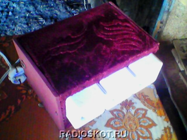
Assembled and checked. Works very well. Here is the device itself in the case:

This is the arrangement of elements inside the box that I chose. It is better to turn it on via a diode bridge. It's cheap. But I think it’s not this that’s important to a radio amateur, but the repetition of the device itself. Even a beginner can solder the circuit. The finished color music device operates without interference, and does not strain the thyristors for a long time. They don't even heat up. Author of the material: Max.
A very simple three-channel RGB color music on LEDs does not contain scarce or expensive components. All elements can be found in anyone, even the youngest radio amateur.
The operating principle of color music is classic and has truly become the most popular. It is based on dividing the sound range into three sections: high frequencies, mid frequencies and low frequencies. Since color music is three-channel, each channel monitors its frequency limit and when its level reaches the threshold value, the LED lights up. As a result, when playing music, a beautiful lighting effect is created when LEDs of different colors blink.
Simple color music scheme
Three transistors - three channels. Each transistor will act as a threshold comparator and when the level exceeds 0.6 Volts, the transistor opens. The transistor load is an LED. Each channel has its own color.In front of each transistor there is an RC circuit that plays the role of a filter. Visually, the circuit consists of three independent parts: the upper part is the high-frequency channel. The middle part is the mid frequency channel. Well, the lowest channel in the diagram is the low-frequency channel.
The circuit is powered by 9 Volts. The input receives a signal from headphones or speakers. If the sensitivity is not enough, then you will need to assemble an amplifier stage on one transistor. And if the sensitivity is high, then you can put a variable resistor at the input and use it to regulate the input level.
You can take any transistors, not necessarily KT805, here you can even install low-power ones like TK315 if the load is only one LED. In general, it is better to use a composite transistor like KT829.
You can also take all the other components of the circuit there.
Assembly of color music
You can assemble the color music using wall-mounted mounting or on a circuit board, as I did.No setup is needed, it’s assembled, and if all the parts are suitable, everything works and blinks without problems.

Is it possible to connect an RGB LED strip to the input?
Of course you can, to do this we connect the entire circuit not to 9 V, but to 12. In this case, we throw out the 150 Ohm quenching resistor from the circuit. We connect the common wire of the tape to plus 12 V, and distribute the RGB channels among the transistors. And, if the length of your LED strip exceeds one meter, then you will need to install transistors on radiators so that they do not fail due to overheating.Color music at work
Looks quite beautiful. Unfortunately, this cannot be conveyed through pictures, so watch the video.Step-by-step assembly of a simple design of LED color music, with a passing study of amateur radio programs
Good afternoon, dear radio amateurs!
Welcome to the website ““
We assemble LED light music (color music).
Part 1.
At today's lesson in Beginning radio amateur school we will start collecting LED light music. During this lesson, we will not only assemble light music, but also study another amateur radio program "Cadsoft Eagle"– a simple, but at the same time powerful, comprehensive tool for the development of printed circuit boards and we will learn how to make printed circuit boards using film photoresist. Today we will choose a circuit, look at how it works, and select the details.
Light and music (color and music) devices were very popular during the Soviet Union. They were mainly three-colored (red, green or yellow and blue) and were most often assembled using the simplest circuits on more or less affordable KU202N thyristors (which, if my memory serves me correctly, cost more than 2 rubles in stores, i.e. were quite expensive) and the simplest audio frequency input filters on coils wound on sections of ferrite rods from radio receivers. They were made mainly in two versions - in the form of three-color spotlights on 220-volt light bulbs, or a special case was made in the form of a box, where a certain number of light bulbs of each color were located inside, and the front of the box was closed with frosted glass, which made it possible to obtain a fancy look on such a screen. light accompaniment of music. Also, ordinary glass was used for the screen, and small fragments of car glass were glued on top of it for better light scattering. It was such a difficult childhood. But today, in the age of the development of incomprehensible capitalism in our country, it is possible to assemble a light and sound device for every taste, which is what we will do.
We will take as a basis LED light circuit diagram published on the website:
To this diagram we will add two more elements:
1. . Since we will have a stereo signal at the input, and in order not to lose sound from any channel, or not to connect two channels directly to each other, we will use the following input node (taken from another light-music circuit):

2. Device power supply . We will supplement the light and music circuit with a power supply assembled on a KR142EN8 microcircuit stabilizer:

This is approximately the set of parts we need to assemble:

LEDs for this device can be used of any type, but they must be super-bright and of different colors. I will use ultra-bright, highly directional LEDs, the light from which will be directed towards the ceiling. You, of course, can use a different option for the light display of the sound signal and use a different type of LEDs:

How does this scheme work? . The stereo signal from the sound source is supplied to the input node, which sums the signals from the left and right channels and feeds it to variable resistances R6, R7, R8, which regulate the signal level for each channel. Next, the signal goes to three active filters, assembled according to an identical circuit using transistors VT1-VT3, which differ only in capacitor values. The meaning of these filters is that they pass through only a strictly defined band of the audio signal, cutting off the unnecessary frequency range of the audio signal from above and below. The upper (according to the diagram) filter passes the band 100-800 Hz, the middle one – 500-2000 Hz and the lower one – 1500-5000 Hz. Using trimming resistors R5, R12 and R16, you can shift the transmitted band in any direction. If you want to obtain other signal bandwidths of the filters, you can experiment with the values of the capacitors included in the filters. Next, the signals from the filters are sent to microcircuits A1-A3 - LM3915. What kind of microcircuits are these?
LM3914, LM3915 and LM3916 chips from National Semiconductors allow you to build LED indicators with various characteristics - linear, stretched linear, logarithmic, special for monitoring an audio signal. In this case, LM3914 is for a linear scale, LM3915 is for a logarithmic scale, and LM3916 is for a special scale. We use LM3915 chips - with a logarithmic scale for monitoring the audio signal.
The initial page of the microcircuit datasheet:

(327.0 KiB, 4,279 hits)
In general, I advise you that when faced with a new, unknown radio component, look for its datasheet on the Internet and study it, especially since there are also datasheets translated into Russian.
For example, what can we glean from the first sheet of the LM3915 datasheet (even with minimal knowledge of English, and in extreme cases, using a dictionary):
- this microcircuit is an analog signal level indicator with a logarithmic display scale and a step of 3 dB;
– you can connect both LEDs and LCD indicators;
– indication can be carried out in two modes: “dot” and “column”;
– maximum output current for each LED – 30 mA;
- and so on…
By the way, what is the difference between a “dot” and a “column”. In the “dot” mode, when the next LED is turned on, the previous one goes out, and in the “column” mode, the previous LEDs do not go out. To switch to the “point” mode, just disconnect pin 9 of the microcircuit from the “+” power source, or connect it to “ground”. By the way, these microcircuits can be used to assemble very useful and interesting circuits.
Let's continue. Since alternating voltage is supplied to the inputs of the microcircuits, the glowing column of LEDs will have uneven brightness, i.e. As the input signal level increases, not only will successive LEDs light up, but their brightness will also change. Below is a table of the threshold activation of each LED for different microcircuits in volts and decibels:

Characteristics and pinout of transistor KT315:

This concludes the first part of the lesson on assembling LED light music and begins to assemble the parts. In the next part of the lesson, we will study the PCB design program “Cadsoft Eagle” and make a printed circuit board for our device using film photoresist.
How to make color music and please your friends? In modern radio engineering there is a huge variety of radio elements and LEDs. Using advances in electronics, radio amateurs can make a DMU with their own hands. A wide range of colors, bright and rich light, high speed of response of various elements, low energy consumption. This list of advantages can be continued endlessly.
The working principle of color music
LEDs assembled according to the circuit blink from an existing sound source (this can be a player or a radio and speakers) at a certain frequency. Benefits of using LEDs before those previously used in installations:
- luminous saturation of light;
- wide color range;
- good speed;
- low energy intensity.
The simplest color schemes
 Simple light music that can be assembled has one LED, powered by a DC source with a voltage of 6 - 12 V. You can assemble a circuit using an LED strip and selecting the necessary transistor. The disadvantage is that there is a dependence of the LED blinking frequency on the sound level. In other words, the full effect can be observed only at one sound level.
If you lower the volume, there will be a rare blinking, and if you increase the volume, a constant glow will remain. This drawback can be eliminated using a three-channel sound converter.
We work according to the simplest circuit using transistors using filters. In order to collect it, 9 volt power supply required, which will allow the LEDs in the channels to glow. To assemble three amplification stages you will need KT315 transistors (analogous to KT3102). Multi-colored LEDs are used as a load. A step-down transformer is used for amplification. Resistors perform the function of adjusting LED flashes. The circuit contains filters for passing frequencies. You can improve the circuit and add brightness; for this, 12 V incandescent light bulbs are used. Control thyristors will be needed. The entire device must be powered from a transformer. Using this simple scheme, you can already work with the filter.
Color music using thyristors, can be assembled even by a novice radio technician. The first thing you need to do is select an electrical circuit. For such an installation, a 12 volt power supply is required. It can work in two modes: as a lamp and as a color music. The mode is selected by a switch installed on the board.
When making light music for your home, you need to make a printed circuit board. To do this, you need to take foil fiberglass with dimensions of 50 x 90 mm and a thickness of 0.5 mm. The board manufacturing process consists of several stages:
- preparation of foil PCB;
- drilling holes for parts;
- drawing paths;
- etching.
The board is ready, components have been purchased. Now the most crucial moment begins - wiring of radio elements. The final result will depend on how carefully they are installed and sealed. We assemble our printed circuit board with components soldered on it into a lampshade that we have at home.
Radioelements for an electrical circuit are quite affordable; it will not be difficult to purchase them at your nearest electrical goods store.
Suitable for color and musical accompaniment wirewound resistors with a power of 0.25 - 0.125 W. The amount of resistance can always be determined by the colored stripes on the body, knowing the order in which they are applied. Trimmer resistors can be both domestic and imported. Capacitors are oxide and electrolytic. Some oxide capacitors may have a polarity that must be observed during installation. Diode bridges are available ready-made, but if there are none, then a rectifier bridge can be easily assembled using diodes of the KD or 1N4007 series. LEDs are ordinary ones with a multi-colored glow. The use of LED RGB strips is a promising direction in radio electronics.
Assembling color music for a car
 If you manage to please with color music from an LED strip with your own hands, then a similar installation with a built-in radio Can be assembled for car. It is easy to assemble and quick to set up. It is proposed to place the set-top box in a plastic case, which can be purchased in the electrical and radio engineering department. The installation is reliably protected from moisture and dust. It is easy to install behind the dashboard of your car. An excellent lighting effect is achieved if you use multi-colored (RGB) tape. The case can also be made independently using plexiglass.
Plates of the required dimensions are selected, two holes are made in the first of the parts (for power supply), and all parts are sanded. We assemble everything using a heat gun. The body is ready.
DIY color music, video:
- Personalized icons of Gregory the Illuminator of Armenia
- Church of the Life-Giving Trinity on Vorobyovy Gory
- Feng Shui of the office - attracting clients and money Feng Shui massage room
- See the meaning of Hirt, August in other dictionaries
- Why do you dream of a watermelon: interpret the meaning of the dream
- What does a young man or guy dream about?
- Dream interpretation of dreams: why do you dream about salt?