DIY LED lamp repair: design, diagram. Repair of LED lamps using examples Design of a 220 volt LED lamp

 Live Journal
 Facebook
 Twitter
In the photo you can see many LED lamps. I got them as a gift. It became possible to study the design of these lamps, electrical circuits, as well as repair these lamps. The most important thing is to find out the reasons for failure, since the service life indicated on the box does not always coincide with the service life.
MR-16 type lamps can be disassembled without any effort.
Judging by the label, the lamp is model MR-16-2835-F27. Its body contains 27 SMD LEDs. They emit 350 lumens. This lamp is suitable for connection to an alternating current network of 220-240 V. Power consumption is 3.5 W. Such a lamp glows white, the temperature of which is 4100 degrees Kelvin and creates a narrowly directed flow due to the flow angle of 120 degrees. The type of base used is “GU5.3”, which has 2 pins, the distance between which is 5.3 mm. The body is made of aluminum, the lamp has a removable base, which is secured with two screws. The glass that protects the lamp from damage is glued at three points.
How to disassemble LED lamp MR-16
To identify the cause of the breakdown, it is necessary to disassemble the lamp body. This is done without much effort.

As you can see in the photo, a ribbed surface is visible on the body. It is designed for better heat dissipation. We insert a screwdriver into one of the ribs and try to lift the glass.

Happened. You can see the printed circuit board, it is glued to the case. Prying it with a screwdriver, it separates.
Repair of LED light bulb MR-16
One of the first to be disassembled was the lamp, the LED inside of which had burned out. The printed circuit board, which is made of fiberglass, burned through.

This lamp will be suitable as a “donor”; the necessary spare parts will be taken from it to repair other lamps. The LEDs on the remaining 9 lamps also burned out. Since the driver is intact, the cause of the breakdown is the LEDs.
Electrical circuit of the LED lamp MR-16
To reduce lamp repair time, it is necessary to create its electrical circuit. It's pretty simple.
Attention! The circuit is connected to the network phase by galvanic means. It is prohibited to use it to power any devices.

How does the scheme work? A voltage of 220 V is supplied to the diode bridge VD1-VD4 through capacitor C1. Then it is supplied to the LEDs HL1-HL27, which are connected in series in the circuit. The number of LEDs can be about 80 pieces. Capacitor C2 (the larger the capacitance, the better) is a smoother for rectified voltage ripples. It eliminates the flicker of light having a frequency of 100 Hz. R1 was set to discharge C1. This is necessary in order to prevent electric shock when replacing the lamp. C2 is protected from breakdown of R2 in the event of an open circuit. R1, R2 do not accept work as such in the circuit.

C1 - red, C2 - black, diode bridge - housing with four legs.
Classic driver circuit for LED lamps up to 5 W
The electrical circuit of the lamps does not have protection elements. You will need a 100-200 ohm resistor, or better yet two. One will be installed in the connection circuit, the second will serve as protection against current surges.

Above is a circuit with protective resistors. R3 protects the LEDs and C2 capacitor, R2 in turn protects the diode bridge. This driver is perfect for lamps whose power is less than 5 W. It will easily power a lamp with 80 SMD3528 LEDs. If you need to reduce or increase the current, manipulate capacitor C1. To eliminate flickering, increase capacity C2.

The efficiency of such a driver is less than 50%. For example, the MR-16-2835-F27 lamp requires a 6.1 kOhm resistor with a power of 4 W. Then the driver will consume power that exceeds the power consumption of the LEDs. Due to the large release of thermal energy, it will not be possible to place it in a small lamp body. In this case, you can separately make a housing for this driver.
It should be remembered that the efficiency of the lamp directly depends on the number of LEDs.
Finding faulty LEDs
After the protective glass has been removed, you can inspect the LEDs. If the slightest black speck is detected on the surface of the LED, it has failed. Inspect the soldering areas and check the quality of the leads. 4 poorly soldered LEDs were found in one of the lamps

LEDs with black dots were marked with a cross. Upon external inspection, the LEDs may be intact. Therefore, you need to call them with a tester. To check, you will need a voltage of a little more than 3 V. A battery, battery, or power supply will do. A current-limiting resistor with a nominal value of 1 kOhm is connected in series behind the power source.

We touch the LED with the probes. In one direction the resistance should be small (the LED can glow), in the other it should be equal to tens of megaohms.

During the test, the lamp must be secured. A bank can come to the rescue.
You can check the LED without special instruments if the device driver is intact. Voltage is applied to the lamp base, the LED leads are short-circuited with tweezers or a piece of wire.

If all LEDs are visible, the shorted one is faulty. But this method is suitable if 1 LED in the circuit fails.
If a failure of several LEDs is detected in the circuit, the lamp will light. Only its luminous flux will decrease. Just short-circuit the pads to which the LEDs were soldered.
Other malfunctions of LED lamps
If upon inspection it turns out that the LEDs are working properly, then the problem is in the driver or the soldering area.

Cold soldering of the conductor was detected in this lamp. Soot, which appeared due to poor soldering, settled on the board tracks. To remove the soot, you needed a cloth moistened with alcohol. The wire was desoldered, tinned and soldered. This lamp worked.
Of all the lamps, one had a driver failure. The diode bridge was replaced by 4 “IN4007” diodes, which are rated for a current of 1 A and a reverse voltage of 1000 V.
Soldering SMD LEDs
To replace a faulty LED, you need to unsolder it without damaging the printed conductors. This can be done with difficulty with a regular soldering iron; it is better to put a tip made of copper wire on the soldering iron.

When soldering the LED, you must pay attention to the polarity. Install the LED at the soldering site, take a 10-15 W soldering iron and heat its ends.
If the LED is burnt and the board is charred, this area should be cleaned. Because it is a conductor. If the pad is delaminated, solder the mono LED to the “neighbors”. This is done if the paths lead exactly to them. Just take a piece of wire, fold it two or three times and solder it.

Analysis of the causes of failure of LED lamps MR-16-2835-F27
According to the table, we can conclude that lamp failures often occur due to failure of LEDs. The reason for this is the lack of protection in the circuit. Although there is space for a varistor on the board.
Repair of LED lamp series “LL-CORN” (corn lamp) E27 4.6 W 36x5050SMD
The technology for repairing a corn lamp differs from the repair of the lamp shown above.

Repairing such a lamp is simple, since the LEDs are located on the body. And dialing does not require any extra steps. This lamp was disassembled purely out of interest.

The technique for checking “corn” is no different from that described above. Only in the body of these lamps there are 3 LEDs. When ringing, all 3 should light up.

If one of the LEDs is found to be broken, short-circuit it or solder in a new one. This will not affect the life of the lamp. The lamp driver does not have an isolating transformer. Therefore, any touching of the LED tracks is unacceptable.
If the LEDs are intact, the problem is in the driver. In order to inspect it, it is necessary to disassemble the body.

To get to the driver, you need to remove the bezel. Pry it with a screwdriver at the weakest point, it should come off.

The driver has the same circuit as our first lamp with the difference that C1-1µF, C2- 4.7 µF. The wires are long, so the driver can be pulled out without effort. After work on replacing the LED, the rim was installed with Moment glue.
Repair of LED lamp “LL-CORN” (corn lamp) E27 12 W 80x5050SMD
Repairing a 12 W lamp is done according to the same scheme. No burnt-out LEDs were found on the case, so I had to open the case to inspect the driver.

There are problems with this lamp. The driver wires were too short and the base had to be removed.

The base is made of aluminum. It was attached to the body using a core. Therefore, it was necessary to drill out the fastening points with a drill whose diameter is 1.5 mm. Next, the base was pryed off with a knife and removed. The wires inside had to be cut.

Inside there were 2 identical drivers, each of which powered 43 diodes.
The driver is wrapped in a heat-shrinkable tube, which had to be cut.

After troubleshooting, the same tube is placed on the driver and crimped with a plastic tie.

The driver circuit includes protection. C1 protects against pulse surges, R2, R3 against current surges. During the testing work, R2 breaks were noticed. Most likely, a voltage exceeding the norm was applied to the lamp. There was no 10 ohm resistor, so a 5.1 ohm resistor was soldered in. The lamp lit up. Next we needed to connect the driver to the socket.

First of all, the short wires were replaced with longer ones. The drivers were connected by supply voltage. To attach the wires to the threaded part of the base, you need to clamp them between the plastic housing and the base.
How to connect to the central contact? Aluminum cannot be soldered, so the wire was soldered to a brass plate in which a hole was drilled for M 2.5. A similar hole was drilled in the contact. The whole thing was screwed together. Next, the base was put on and secured to the lamp body with a cap. The lamp was operational.
Repair of LED lamp series “LLB” E27 6 W 128-1

The design of the lamp is ideal for repairs. The housing is easy to disassemble.

You should hold the base with one hand and turn the protective shade counterclockwise with the other.

Under the body there are five rectangular boards on which LEDs are soldered. The rectangle is soldered to a round board on which the driver circuit is located.

To gain access to the LED terminals, you need to remove one of the covers. To make work easier, it is better to remove the board located at the driver voltage supply points. The photo shows that this wall is parallel to the capacitor body and is separated from it at the maximum distance.

To remove the board, you need to warm up the soldering areas with a soldering iron. Then, to remove it, we heat up the soldering on the round board and it disconnects.

Access to check damage is open. The driver is designed according to a simple design. Checking its rectifier diodes, as well as all the LEDs (there are 128 of them in this lamp) did not show a problem.

When I inspected the solder joints, I discovered that they were missing at some points. These places were soldered; in addition, I connected the printed circuit board tracks in the corners.
When you look at the light, these paths are clearly visible and you can easily determine which path is which.

Before assembling the lamp, it was necessary to test it. To do this, a jumper was installed on the board, and the soldered part of the lamp was connected to the power source with two temporary wires.

The lamp lit up. All that remains is to solder the board in its original place and assemble the lamp.
Repair of LED lamp series “LLB” LR-EW5N-5
In appearance, the lamp is made with high quality. The body is aluminum and the design is beautiful.

The lamp is assembled securely. Therefore, to disassemble it, you need to remove the protective glass. To do this, insert the end of a screwdriver between the radiator. The glass is fixed here without glue, with a collar. You need to rest the screwdriver on the end of the radiator and lift the glass up, using the screwdriver as a lever.


The tester did not show any failure of the LEDs. So it's all about the driver. To get to it, you need to unscrew 4 screws.

But failure overtook me. Behind the board there was a radiator plane. It is lubricated with a paste that conducts heat. I had to collect everything I had unwound. I decided to disassemble the lamp from the base side.

In order to remove the base, I had to drill out the core points. But he didn't act. As it turned out, it was fastened to plastic with a threaded connection.

The radiator had to be separated from the plastic adapter. To do this, I cut with a hacksaw in the place where the plastic was attached to the radiator. Then, by turning the screwdriver, the parts were separated from one another.

The pins were unsoldered from the LED board, which made it possible to work with the driver. Its circuit was more complex compared to other drivers. Upon inspection, a swollen capacitor 400 V 4.7 µF was found. It has been replaced.

The Schottky diode "D4" type SS110 was damaged. It's at the bottom left of the photo. It was replaced by the analogue "10 BQ100", which has 1 A and 100 V. The light bulb lit up.
Repair of LED lamp series “LLB” LR-EW5N-3
The lamp is similar to the "LLB" LR-EW5N-5, but its design has been changed.

The protective glass is secured with a ring. If you pick up the junction of the ring and the glass, it can be easily removed.

The printed circuit board is made of aluminum. There are nine crystal LEDs on it, numbering 3 pieces. The board is secured with 3 screws to the heatsink. The check did not reveal any problems with the LEDs. So it's a driver issue. Experience in repairing a similar lamp has shown that it is better to immediately unsolder the wires that come from the driver. The lamp was disassembled from the base side.

The ring connecting the base and the radiator was removed with great effort. At the same time, a piece broke off. And all because it was screwed with 3 screws. The driver has been removed.

The screws are located under the driver; you can reach them with a Phillips screwdriver.

This driver is based on a transformer circuit. The check showed the serviceability of all parts except the microcircuit. I didn't find any information about her. The lamp was set aside as a donor.
Repair of LED lamp series "LLC" E14 3W1 M1
This lamp is similar to an incandescent lamp. The first thing you notice is the wide metal ring.
I started disassembling the lamp. The first step was to remove the lampshade. As it turned out, it was placed on the base with an elastic compound. After I took it off, I realized that it was in vain.

The lamp contained 1 LED, the power of which was 3.3 W. It could be checked from the base side.

The lamp was attached to the body using a “left-hand” thread. You need to rotate the base counterclockwise when looking at it from the side of the central contact.

The cause of the breakdown was a wire that fell off the thread on the base. You can't solder aluminum, so you had to look for a way to fasten the wire.

A 5 cm piece was soldered to the existing wire for extension. A hole was drilled at the core point, the diameter of which was 2 mm. A wire was threaded through it and wound around a screw. The screw itself was inserted into the hole and clamped with a nut. This lamp glowed like new.
Repair of LED lamp series “LL” GU10-3W
The “LL” type lamp GU10-3W was difficult to disassemble in appearance. The glass began to crack the moment I tried to remove it.

What does the marking mean?
- G - presence of a pin socket;
- U - energy saving lamp;
- 10 – size between pins (measured in mm)

Thanks to the expansion pins, the lamp is held firmly in the socket.

This lamp could be disassembled using a drilled hole. The drilling location was at the level of the printed circuit board. The diameter was chosen to be 2.5 mm. When drilling, you need to take into account the fact that the drill can damage the LED. If you don’t have a drill, you can make a hole with an awl.

A screwdriver is inserted into the hole made. Using it as a lever, you need to lift the glass. If no problems are found when checking the LEDs, remove the printed circuit board.

Burnt 160 ohm resistors were found in both lamps. Based on their size, it could be established that their power is 0.25 W. It does not correspond to the power that is released when the lamp is operating.

The board was filled with silicone, I did not disconnect it. I replaced the burnt resistors with more powerful ones. In one lamp I used a resistor of 150 Ohms and 1 W, in the other 2 parallel soldered ones of 320 Ohms and 0.5 W.

To avoid short circuits, the resistor terminals were coated with silicone. It acts as an insulator.

You can find 2 types of silicone on the market: liquid in tubes and solid, shaped like a rod. The good thing about the rod is that it can be separated with a soldering iron and applied to the desired surface. After hardening it becomes strong.

Both lamps were glowing. All that remains is to attach the board and put on the protective glass.

To secure the boards, I use liquid nails “Mounting” moment. After drying, this glue has plasticity and good heat resistance.

The glue is applied with a screwdriver. In about 15 minutes he will hold our part.
In order not to hold the board until the glue has completely dried, I fix it with silicone at some points. The glass was glued using liquid nails, and the lamp became operational.
The design of 220V LED lamps in many cases varies depending on the design features laid down by the manufacturer.
However, knowledge of the main types of devices allows you to independently determine the cause of the malfunction of the lighting device, as well as perform some simple repair work yourself.
Let's look at what LEDs are used in lamps. Currently, there are a huge number of subspecies and groups that are types of LED lighting devices, but the most basic types include the following:

- Low current super bright source and SMD LED. Such options are very often used as indicators. The LED can be assembled on one chip without using a lens or on several chips using a common lens.
- COB module is square or linear with a white glow, which makes this type popular in floodlights and lanterns used in street lighting.
- Filament is a rod version, reaching a quarter of a meter in length and consisting of a very large number of crystals. The filament type is especially popular in the production of 220V filament lamps.
- Display-type OLED LEDs, characterized by a very characteristic thin-film and organic structure.
No less popular are LEDs, which are used in the manufacture of remote control, as well as lamps for medical or cosmetic purposes.
Thus, regardless of the typical features, the main components of the LED lamp are represented by the base part, the built-in driver or current stabilizer, the diffuser housing, and also the light-emitting diodes themselves.
Assembly methods
Today, several methods of assembling lighting elements are practiced, thanks to which a certain classification of modern LEDs has been created.
DIP
 The Dual In-line Рaskage option is an interesting, from a design point of view, but outdated type, characterized by the following LED sizes:
- 0.3 cm;
- 0.5 cm;
- 0.8 cm;
- 1.0 cm.
In addition to the size of the bulb, semiconductors differ markedly in color and materials used for manufacturing, as well as in the shape of the chip. The main advantages of this type of LEDs include low heating and decent brightness.
Dual In-line Рaskage are available in both single-color and RGB versions, and most often have a very characteristic cylindrical shape, and have a built-in convex lens.
"Piranha"
LEDs belonging to this group are characterized by the best luminous qualities in terms of luminous flux. The design feature is represented by a rectangular shape and the presence of four special pins. Available in red, green, blue and white.
One of the main differences is the possibility of a more “rigid” fixation on the board, and the very high thermal conductivity is due to the lead substrate.

LED lamp Piranha Chameleon (RGB)
The presence of lead calls into question the safety of operation, but the wide range of operating temperatures allows the use of high input powers, which determines its wide popularity.
SMD technology
 SMD LEDs, also known as Surface Mounting Device or “device fixed on a surface,” have a power of 0.01-0.2 W.
A feature of SMD LEDs is the presence of one, two or three modern crystals on ceramic rectangular bases.
SMD LEDs are coated with an individually high-quality phosphor layer. The contact pads and the circuit board base are directly connected using standard solder.
The disadvantages of this modern technology include the low maintainability of the design, as well as the need to completely replace the board with all LEDs if one of them fails.
COB technology
Modern manufacturing technology for LED lamps, called Chip On Board, is characterized by fixing crystals on a board without a housing or ceramic substrate, and coating with a common phosphor. The main advantage of any COB illuminators is the minimum luminous area with increased power levels.

LED COB lamp
The high placement density and the presence of a general coating with a layer of phosphor guarantee the most uniform glow of the lighting device.
 Among economical lamps, fluorescent lamps were first widely used, but now LED lamps are increasingly preferred. – this information will be useful for those who decide to replace light bulbs.
Read about how to select and install a transformer for an LED strip.
Types and methods of connecting a dimmer for LED lamps are described.
LED lamp design
Depending on the purpose of the lighting device and the characteristics of the production lines of the manufacturer, the design of the LED light bulb may have some quite noticeable differences that should be taken into account when choosing.

LED lamp device
Branded products
The design features of 220V LED lamps, which are produced by world-famous manufacturers, are the presence of the following mandatory components:
- light-scattering hemisphere;
- chips;
- an aluminum printed circuit board with a paste of sufficient thermal conductivity, which allows you to regulate the performance of the chips;
- radiators based on anodized aluminum alloy;
- a driver having a galvanically isolated modulator circuit;
- polymer base of the base in the form of polyethylene terephthalate;
- base part with nickel coating.
It should be noted that the driver has an increased installation density of such parts as a pulse-type transformer, microcircuits and polar capacitors, as well as various planar elements.
Low quality Chinese light bulbs
 It is the insufficiently high quality and the absence of a number of elements that explains the low cost of LED light sources produced by the Chinese manufacturer:
- lack of radiator;
- lack of driver;
- the presence of a simple power supply in the form of a non-polar capacitor;
- lack of reliable stabilization of the output current.
The power supply unit is installed in the central part of the board with light diodes. On one side there is a diode bridge and resistors, and on the other there is a pair of capacitors.
The cooling process in Chinese light sources is carried out through pinpoint, ineffective holes in the housing, which becomes the main reason for the frequent burnout of crystals.
Filament lamps
The design feature of the “filament lamp” is the presence of the main components, represented by:- LED bars;
- glass flask;
- metal base part;
- driver board.
As an addition, we can consider the presence of a base for the base part.
Thus, an LED filament can be thought of as a rectangular or round glass rod containing miniature LED chips.
Applying a thick silicone layer of yellow phosphor to each element helps prevent the passage of ultraviolet rays, and also allows for the most uniform dispersion of the light flux.
Connection diagram
As practice shows, despite the rather high cost, the total consumption of electrical energy by semiconductor lighting devices is significantly lower than that of standard incandescent light bulbs, and the average service life, on the contrary, is about five times longer.

LED lamp wiring diagram
The connection diagram for such a light source is very simple. The LED lamp operates under 220V supply conditions, as a result of the driver converting the input signal to operating values, causing the glow.
Video on the topic
Implementation projects are increasingly incorporating LED components. LED fixtures have gained widespread popularity due to significant energy savings and durability, although their cost still exceeds the price tags of more conventional energy-saving and halogen lamps. But LED technology has many other advantages due to its unusual design. A typical 220 device, the photo of which is presented below, is free of massive radiation sources, which allows the body to be optimized in size and performance characteristics. As a result, such qualities as wide functionality, increased ergonomics of control and ease of installation are achieved.
Diode crystal as the basis of a lamp
The basis of any LED device is formed by one or more semiconductor elements that convert electricity into light radiation. These are diode crystals, most often made in the form of a miniature chip. On a small platform of the board there is also equipment for connecting power wires. However, a 220 V device may involve the use of different crystals that differ in design and set of functional components:
- DIP. The most common one is on the surface of which a lens and two conductors are placed.
- SMD. A universally applicable crystal, characterized by its modest size and effective heat dissipation.
- "Piranha". Diode crystal with four outputs for occasions. This configuration makes the emitter more efficient and reliable in operation.
- OWL crystal. In this case, a diode is integrated into the board, due to which the contacts are better protected from overheating and oxidation. At the same time, the intensity of the glow increases.

Basic design of a 220 V LED lamp
In addition to diode crystals, the design includes a base, diffuser, radiator and housing. The board itself with LED elements is the functional core, which is served by the listed components. As for the base, it acts as a supporting link that allows you to integrate the lamp into a socket of a suitable size. The scatterer makes the photon radiation (converted from the current) more saturated and directed. In more modern versions, it is possible to change the physical parameters of the light supply, which is achieved precisely by adjusting the parameters of the diffuser. The radiator unit is also essential in the design of a 220 V LED lamp. One of the main advantages of LED devices is the absence of heating of the housing, which makes the source fireproof. This property is provided precisely by the radiator, which performs the task of heat removal.
Features of low-power lamps
The entry level in the segment is represented by compact devices with 2-4 crystals. The power of each emitter varies from 2 to 5 W. Unlike full-size models, such lamps are characterized by the presence of a plastic body (in conventional designs glass covers are used), a modest length of about 15 cm on average and a weight of 50-70 grams. At the same time, the design of low-power 220 V LED lamps also requires the presence of radiator units. These can be massive metal modules, the task of which is to protect the plastic case from overheating and melting. In this case, the requirements for heat dissipation are much more stringent, so the size of the radiator is often larger than in high-power LED lamps. As for the quality of radiation, users note the mutedness of the light, more gravitating towards bright white and cold spectra.
Lamp shapes and sockets

Especially when choosing non-standard designs, it is important to calculate in advance the possibility of combining a lamp with a lamp in the form of a chandelier, sconce, floor lamp, etc. The most popular form factors include the following:
- LED pear. Standard design that resembles classic incandescent lamps. For such models, E27 type sockets are selected.
- Candle shape. It is on this housing that the device of low-power 220-volt LED lamps, including E14 and E27 sockets, is based. Similar designs are often used in wall lamps and small chandeliers.
- Tubular shape. This is already a non-standard version of the lamp, marked with the designations T3, T4, T20, etc. However, the external resemblance to fluorescent lamps does not in any way transfer to the internal filling, much less to the working qualities.
- Ball-shaped models. For such devices, bases G45, G60 and G80 are used, which can be integrated into different types of luminaires, both open and closed.
Control driver device

This component is not always used, but 220-volt models are the target devices. For them, devices with the HV9910 microcircuit are usually used, which can be powered from a network with a voltage of 8 to 450 V. The microcircuit itself acts as a pulse source that equalizes the current. If you plan to use alternating current for power supply, then the 220 V LED lamp driver device will also have to include a rectifier - for example, a bridge type. In common configurations of this type, the HV9910 driver also works in combination with external transistors.
Features of “Armstrong” type structures
The commercial use of lighting devices places high demands on the supporting structures into which the lamps are integrated. This is due to the need to improve protective qualities and to technical optimization of the installation process. At the moment, such problems are solved by Armstrong-type platforms, which are a ceiling structure designed for several powerful radiation sources. Unlike standard models, the 220 V LED lamp device for the Armstrong design has the following characteristics:
- Clogging the lamp into a plastic monolithic housing.
- The use of technologically primitive drivers (in order to reduce the cost of design) or their complete absence.
- Using one radiator for several lamps.
- Typical design of the supporting platform, which involves the provision of standard plinths.
Lamp control system

Modern LED devices are equipped with dimmers, through which you can adjust the operating parameters of the lamp. In particular, the user can set brightness parameters. Some versions also include programming elements. Using the built-in timer, you can set the time, glow modes and work sessions with specific glow characteristics. A typical 220 V with a dimmer also includes a stabilizer. The fact is that the brightness is adjusted by cutting the voltage and to reliably perform this procedure, a stabilizing component is required. Also, to ensure safety under conditions of maximum power, a safety unit is often used, the range of functions of which includes automatically turning off the device or switching it to a balanced operating mode.
How to make your own LED lamp?
The simplest technique for manufacturing this device is based on a burnt out or unnecessary fluorescent lamp. It is necessary to disassemble its structure, removing the base with the reflector. These parts contain the most important elements from the point of view of the device; the entire electrical circuit is disassembled, during which the fuse, as well as the diode crystal, should be removed from the reflector. Actually, the new lamp will be based on ready-made lighting equipment, the filling of which can be assembled using an electrolyte. But before this, you should add to the configuration a capacitor unit capable of withstanding at least 450 V, and better yet, 630 V. And if there are not enough LEDs, they can be taken from an LED strip. The main thing is to choose components of appropriate power. The assembly of the structure is carried out using superglue or a compound with suitable characteristics.

Lamp installation
The installation approach will depend on the design of the luminaire. The most difficult in terms of installation are ceiling structures, in the niches of which a lamp is integrated. These are high-power point devices that subsequently operate without lampshades. That is, a barely noticeable part of the optical emitter remains on the surface of the tension or hanging installation. For ease of installation, a 220-volt LED lamp of this type provides fixing rings and clamps. With the help of this fittings, the housing is fastened to the ceiling niche. But before this, an electrical line with a socket into which it will be screwed must be connected to the placement point on the side of the frame. Next, the mounting hardware with the lamp is inserted into the hole made in the hanging or tension fabric and closed.
Maintenance minimizes the risks of capital repairs with replacement of diodes. This point can be delayed in time by regularly cleaning the device and updating consumables. If insufficient brightness is observed during operation of the device, this is a sign of failure of an individual crystal or an entire group. The nature of the malfunction is precisely determined by the design of the 220 V LED lamp. How to repair devices that have similar problems? First of all, you need to carry out diagnostics and identify specific areas of malfunction. Irretrievably damaged diodes usually have black dots on the surface. They should be dismantled, the place cleaned and new crystals installed. The problem will be that the emission spectrum of diodes may differ even with nominally similar parameters, so difficulties arise in selecting the optimally appropriate emitter.
Conclusion

The use of LED lamps justifies itself both in the industrial sphere and in everyday life. If at the dawn of this technology its advantages in the form of energy savings and long service life came to the fore, today control capabilities are increasingly valued. However, new problems also arise, also caused by the multi-component design of the 220 V LED lamp. Repair in the event of serious breakdowns requires the need to completely disassemble the product and then resolder the conductors. At least this applies to diode replacement operations. The system also includes drivers, controllers and fuses. These electrical fittings also often fail. But these disadvantages can also be minimized by using not cheap Chinese LED components, but products from companies like Osram or Philips.
Despite the diversity on the country's shelves, they remain unrivaled due to their cost-effectiveness and durability. However, a quality product is not always purchased, because in a store you cannot take the product apart for inspection. And even in this case, it is not a fact that everyone will determine from what parts it is assembled. burn out, and buying new ones becomes expensive. The solution is to repair LED lamps yourself. Even a novice home craftsman can do this work, and the parts are inexpensive. Today we will figure out how to check in what cases the product is repaired and how to do it.
It is known that LEDs cannot operate directly from a 220 V network. To do this, they need additional equipment, which, most often, fails. We'll talk about it today. Let's consider the circuit, without which the operation of the lighting device is impossible. At the same time, we will conduct an educational program for those who do not understand anything about radio electronics.

driver gauss 12w
The 220 V LED lamp driver circuit consists of:
- diode bridge;
- resistance;
- resistors.
The diode bridge serves to rectify the current (converts it from alternating to direct). On the graph it looks like cutting off a half-wave of a sine wave. Resistors limit the current, and capacitors store energy, increasing the frequency. Let's look at the operating principle of a 220 V LED lamp.
The principle of operation of the driver in an LED lamp
| View on the diagram | Operating procedure |
 | A voltage of 220 V is supplied to the driver and passes through a smoothing capacitor and a current-limiting resistor. This is necessary in order to protect the diode bridge. |
 | Voltage is supplied to a diode bridge, consisting of four differently directed diodes, which cut off the half-wave of the sine wave. The output current is constant. |
 | Now, by means of a resistance and a capacitor, the current is again limited and the desired frequency is set. |
 | Voltage with the necessary parameters is supplied to unidirectional light diodes, which also serve as a current limiter. Those. when one of them burns out, the voltage increases, which leads to failure of the capacitor if it is not powerful enough. This happens in Chinese products. High-quality devices are protected from this. |
Having understood the principle of operation and the driver circuit, the decision on how to repair a 220V LED lamp will no longer seem difficult. If we talk about quality products, then you shouldn’t expect any troubles from them. They work for the entire prescribed period and do not fade, although there are “diseases” to which they are also susceptible. Let's talk about how to deal with them now.
Reasons for failure of LED lighting devices
To make it easier to understand the reasons, let’s summarize all the data in one common table.
| Cause of failure | Description | Solution |
| Voltage drops | Such lamps are less susceptible to breakdowns due to voltage surges, however, sensitive surges can “break through” the diode bridge. As a result, the LED elements burn out. | If surges are sensitive, you need to install one, which will significantly extend the life of the lighting equipment, but also other household appliances. |
| Incorrectly selected lamp | Lack of proper ventilation affects the driver. The heat it generates is not removed. The result is overheating. | Choose one with good ventilation that will provide the necessary heat exchange. |
| Installation errors | Incorrectly selected lighting system and its connection. Incorrectly calculated electrical wiring cross-section. | Here the solution would be to unload the lighting line or replace lighting fixtures with devices that consume less power. |
| External factor | Increased humidity, vibration, shock or dust if the IP is incorrectly selected. | Correct selection or elimination of negative factors. |
Good to know! Repair of LED lamps cannot be carried out indefinitely. It is much easier to eliminate negative factors that affect durability and not purchase cheap products. Savings today will result in costs tomorrow. As economist Adam Smith said, “I am not rich enough to buy cheap things.”

Repairing a 220 V LED lamp with your own hands: nuances of the work
Before you repair an LED lamp with your own hands, pay attention to some details that require less labor. Checking the cartridge and the voltage in it is the first thing to do.
Important! Repairing LED lamps requires a multimeter - without it you will not be able to ring the driver elements. You will also need a soldering station.
household multimeters
A soldering station is necessary for repairing LED chandeliers and lamps. After all, overheating of their elements leads to failure. The heating temperature when soldering should be no higher than 2600, while the soldering iron heats up more. But there is a way out. We use a piece of copper wire with a cross-section of 4 mm, which is wound onto the soldering iron tip in a tight spiral. The more you lengthen the tip, the lower its temperature. It is convenient if the multimeter has a thermometer function. In this case, it can be adjusted more accurately.
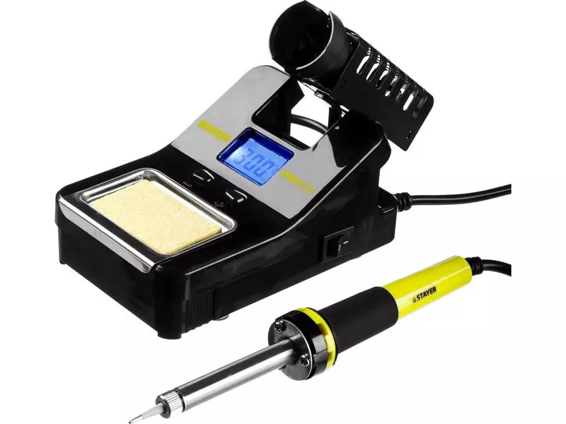
Soldering Station
But before you repair LED spotlights, chandeliers or lamps, you need to determine the cause of the failure.
How to disassemble an LED light bulb
One of the problems that a novice home DIYer faces is how to disassemble an LED light bulb. To do this you will need an awl, solvent and a syringe with a needle. The LED lamp diffuser is glued to the body with sealant, which needs to be removed. Carefully running an awl along the edge of the diffuser, inject the solvent with a syringe. After 2-3 minutes, easily twisting, the diffuser is removed.

Some lighting fixtures are made without sealant. In this case, it is enough to rotate the diffuser and remove it from the body.
Determining the cause of failure of an LED light bulb
After disassembling the lighting fixture, pay attention to the LED elements. Burnt is often identified visually: it has scorch marks or black dots. Then we replace the faulty part and check its functionality. We will tell you in detail about the replacement in step-by-step instructions.
If the LED elements are in order, move on to the driver. To check the functionality of its parts, you need to remove them from the printed circuit board. The value of resistors (resistance) is indicated on the board, and the parameters of the capacitor are indicated on the case. When testing with a multimeter in the appropriate modes, there should be no deviations. However, often failed capacitors are identified visually - they swell or burst. The solution is to replace it with suitable technical parameters.

Replacing capacitors and resistances, unlike LEDs, is often done with a regular soldering iron. In this case, care should be taken not to overheat nearby contacts and elements.
Replacing light bulb LEDs: how difficult is it?
If you have a soldering station or hair dryer, this work is simple. It is more difficult to work with a soldering iron, but it is also possible.
Good to know! If you don’t have working LED elements at hand, you can install a jumper instead of the burnt one. Such a lamp will not work for a long time, but it will be possible to gain some time. However, such repairs are carried out only if the number of elements is more than six. Otherwise, a day is the maximum work of the repair product.
Modern lamps operate on SMD LED elements, which can be desoldered from the LED strip. But it is worth choosing the ones that are suitable according to technical characteristics. If there are none, it is better to change everything.

Related article:
To choose the right LED devices, you need to know not only the general ones. Information about modern models and electrical diagrams of working devices will be useful. In this article you will find answers to these and other practical questions.
Repairing an LED lamp driver if you have an electrical diagram of the device
If the driver consists of SMD components that are smaller in size, we will use a soldering iron with copper wire on the tip. A visual inspection revealed a burnt element - unsolder it and select the appropriate one according to the markings. There are no visible damages - this is more difficult. You will have to solder all the parts and ring them separately. Having found a burnt one, we replace it with a functional one. It is convenient to use tweezers for this.
Helpful advice! You should not remove all elements from the printed circuit board at the same time. They are similar in appearance, you can later confuse the location. It is better to unsolder the elements one by one and, after checking, mount them in place.

How to check and replace the power supply of LED lamps
When installing lighting in rooms with high humidity (or), stabilizing ones are used, which reduce the voltage to a safe one (12 or 24 volts). The stabilizer can fail for several reasons. The main ones are excessive load (power consumption of luminaires) or incorrect selection of the unit’s degree of protection. Such devices are repaired in specialized services. At home, this is unrealistic without equipment and knowledge in the field of radio electronics. In this case, the power supply will have to be replaced.

LED power supply
Very important! All work to replace the stabilizing LED power supply is carried out with the voltage removed. Don't rely on the switch - it may not be connected correctly. The voltage is turned off in the apartment's distribution panel. Remember that touching live parts with your hand is dangerous.
You need to pay attention to the technical characteristics of the device - the power must exceed the parameters of the lamps that are powered from it. Having disconnected the failed unit, we connect a new one according to the diagram. It is located in the technical documentation of the device. This does not present any difficulties - all wires are color-coded, and the contacts are labeled with letters.
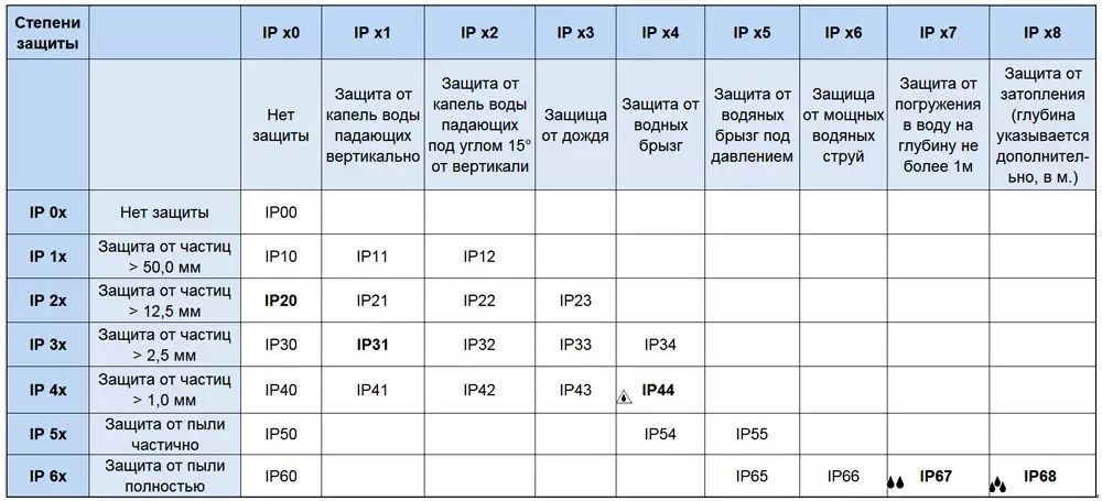
The degree of protection of the device (IP) also plays a role. For a bathroom, the device must be marked at least IP45.
Article
Despite the high cost, the energy consumption of semiconductor lamps (LED) is much less than that of incandescent lamps, and their service life is 5 times longer. The LED lamp circuit operates with a supply of 220 volts, when the input signal causing the glow is converted to an operating value using a driver.
LED lamps 220 V
Whatever the supply voltage, a constant voltage of 1.8-4 V is supplied to one LED.
Types of LEDs
An LED is a semiconductor crystal made of several layers that converts electricity into visible light. When its composition changes, radiation of a certain color is obtained. The LED is made on the basis of a chip - a crystal with a platform for connecting power conductors.
To reproduce white light, the “blue” chip is coated with a yellow phosphor. When the crystal emits radiation, the phosphor emits its own. Mixing yellow and blue light creates white.
Different chip assembly methods allow you to create 4 main types of LEDs:
- DIP - consists of a crystal with a lens located on top and two conductors attached. It is the most common and is used for lighting, lighting decorations and displays.
- “Piranha” is a similar design, but with four terminals, which makes it more reliable for installation and improves heat dissipation. Mostly used in the automotive industry.
- SMD LED - placed on the surface, due to which it is possible to reduce dimensions, improve heat dissipation and provide many design options. Can be used in any light sources.
- COB technology, where the chip is soldered into the board. Due to this, the contact is better protected from oxidation and overheating, and the glow intensity is significantly increased. If an LED burns out, it must be completely replaced, since DIY repairs by replacing individual chips are not possible.
The disadvantage of the LED is its small size. To create a large, colorful light image, many sources are required, combined into groups. In addition, the crystal ages over time, and the brightness of the lamps gradually decreases. For high-quality models, the wear process is very slow.
LED lamp device
The lamp contains:
- frame;
- base;
- diffuser;
- radiator;
- LED block;
- transformerless driver.

220 volt LED lamp device
The figure shows a modern LED lamp using SOV technology. The LED is made as one unit, with many crystals. It does not require wiring of numerous contacts. It is enough to connect just one pair. When a lamp with a burnt-out LED is repaired, the entire lamp is replaced.
The shape of the lamps is round, cylindrical and others. Connection to the power supply is made through threaded or pin sockets.
For general lighting, luminaires with color temperatures of 2700K, 3500K and 5000K are selected. The spectrum gradations can be any. They are often used for advertising lighting and for decorative purposes.
The simplest driver circuit for powering a lamp from the mains is shown in the figure below. The number of parts here is minimal, due to the presence of one or two quenching resistors R1, R2 and the back-to-back connection of LEDs HL1, HL2. This way they protect each other from reverse voltage. In this case, the flickering frequency of the lamp increases to 100 Hz.

The simplest diagram for connecting an LED lamp to a 220 volt network
The supply voltage of 220 volts is supplied through the limiting capacitor C1 to the rectifier bridge, and then to the lamp. One of the LEDs can be replaced with a regular rectifier, but the flickering will change to 25 Hz, which will have a bad effect on vision.
The figure below shows a classic LED lamp power supply circuit. It is used in many models and can be removed for DIY repairs.

Classic scheme for connecting an LED lamp to a 220 V network
The electrolytic capacitor smooths out the rectified voltage, which eliminates flicker at a frequency of 100 Hz. Resistor R1 discharges the capacitor when the power is turned off.
DIY repair
A simple LED lamp with individual LEDs can be repaired by replacing faulty elements. It can be easily disassembled if you carefully separate the base from the glass body. There are LEDs inside. The MR 16 lamp has 27 of them. To access the printed circuit board on which they are located, you need to remove the protective glass by prying it off with a screwdriver. Sometimes this operation is quite difficult to do.

LED lamp 220 volts
Burnt-out LEDs are immediately replaced. The rest should be ringed with a tester or a voltage of 1.5 V should be applied to each. The serviceable ones should light up, and the rest must be replaced.
The manufacturer calculates the lamps so that the operating current of the LEDs is as high as possible. This significantly reduces their service life, but it is not profitable to sell “eternal” devices. Therefore, a limiting resistor can be connected in series to the LEDs.
If the lights blink, the cause may be a failure of capacitor C1. It should be replaced with another one with a rated voltage of 400 V.
Make it yourself
LED lamps are rarely made again. It is easier to make a lamp from a faulty one. In fact, it turns out that repair and production of a new product is one process. To do this, the LED lamp is disassembled and the burnt-out LEDs and driver radio components are restored. There are often original lamps on sale with non-standard lamps, which are difficult to find replacements in the future. A simple driver can be taken from a faulty lamp, and LEDs from an old flashlight.
The driver circuit is assembled according to the classic model discussed above. Only resistor R3 is added to it to discharge capacitor C2 when turned off and a pair of zener diodes VD2, VD3 to bypass it in case of an open circuit of the LEDs. You can get by with one zener diode if you choose the right stabilization voltage. If you select a capacitor for voltages greater than 220 V, you can do without additional parts. But in this case, its dimensions will increase and after the repair is done, the board with the parts may not fit into the base.

LED lamp driver
The driver circuit is shown for a lamp of 20 LEDs. If their number is different, it is necessary to select a capacitance value for capacitor C1 such that a current of 20 mA passes through them.
The power supply circuit for an LED lamp is most often transformerless, and care should be taken when installing it yourself on a metal lamp so that there is no phase or zero short circuit to the housing.
Capacitors are selected according to the table, depending on the number of LEDs. They can be mounted on an aluminum plate in the amount of 20-30 pieces. To do this, holes are drilled in it, and LEDs are installed on hot-melt adhesive. They are soldered sequentially. All parts can be placed on a printed circuit board made of fiberglass. They are located on the side where there are no printed tracks, with the exception of LEDs. The latter are attached by soldering the pins on the board. Their length is about 5 mm. The device is then assembled in the luminaire.

LED table lamp
220 V lamp. Video
You can learn about making a 220 V LED lamp with your own hands from this video.
A properly made homemade LED lamp circuit will allow you to operate it for many years. It may be possible to repair it. Power sources can be any: from a regular battery to a 220-volt network.
- Repair of LED lamps using examples Design of a 220 volt LED lamp
- Device for testing transistors (betnik) Homemade probe for transistors
- How to make a watch with your own hands - ideas and master class Homemade wristwatches
- We assemble a simple power regulator circuit for a soldering iron with our own hands
- Interskol 14 screwdriver diagram
- Metal detectors operating on the principle of pulse induction Block diagram of a pulse metal detector
- Do-it-yourself deep metal detector: diagram, instructions and reviews What is the best balanced or pulse metal detector