Voltmeter ammeter from china revision of the power supply. We connect a Chinese digital voltammeter

 Live Journal
 Facebook
 Twitter
I decided to write this article when I was making a power supply for my home laboratory. From my own experience, it was noticed that the regulated power supply should have voltmeter, to estimate the voltage to be set. And ampermetr, for a rough estimate of the current consumed by the load. Resolved in new source power supply, install these useful elements: a voltmeter and an ammeter. Looking in the boxes, I found two suitable measuring heads (the main criterion is the minimum dimensions). With a maximum current of 50μA and 30mA.
First let's do voltmeter from ammeter
So let's move on to the calculations.
The easiest thing is to make a voltmeter from an ammeter, I use a second ammeter. For calculations, we need: the maximum deflection current of the arrow - in my case 30mA, The maximum voltage that our voltmeter should measure is 30V.
Using ohm's law we find resistance: R \u003d U / I, R \u003d 1kOhm.
Means shunt (resistor) with a resistance of 1 kOhm must be connected in series with an ammeter. This gives us a voltmeter. Those. if a current of 30mA flows through such a series circuit, then the voltage drop across this resistor is 30V. In my case, I don't even need to change the scale of the instrument, just stick the letter "V" to make it clear that this is a voltmeter.
It should be remembered that a current of 0-30mA will always flow through such a voltmeter, depending on the measured voltage from 0-30V. And since it is used in the power supply, this is not critical. Also, do not forget that the resistor must be of a suitable capacity, which we determine by the formula P \u003d I * I * R we get P \u003d 30mA * 30mA * 1kΩ \u003d 0.9W, set with a margin of at least 1W.
We must also take into account internal resistance device. Then the additional resistor is considered as follows: Rd \u003d Up / Ii-Ri.
Rd is the resistance of the additional resistor;
Uп - max. the value of the selected voltage measurement limit;
Ii is the total deflection current of the selected ammeter;
Ri - internal resistance (device frame) of the selected ammeter, it is indicated.
We do ammeter from ammeter which has a small scale.
The first ammeter has a scale of 50μA, this is very small, I need 1.5A. To expand the measuring range of the ammeter, you need to install a shunt, but not in series, but in parallel with the measuring head. It turns out that the current will branch out and one part will flow through the ammeter, and the other through the resistance. It is necessary to choose such a resistance so that the current of 1.5A is divided by two, 50mkA through the ammeter, and the rest of the current through the resistor.
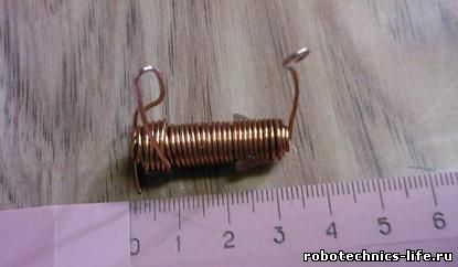
For calculations, you will need to know the resistance of the ammeter, but since I do not know it, the shunt will be made by the fitting method. To do this, you need to take a copper wire with a diameter of 0.8-1 mm and a length of 1 meter and measure the current at which the arrow deviates to the extreme position.

This will require a regulated voltage source and load, I used a car light bulb. Further, in this way we adjust the shunt by increasing the length of the wire if you need to reduce the maximum current or shorten the wire if you need to increase the maximum value of the ammeter scale.

I got such a shunt in four layers. I glued the edges with silicone glue.
It should be remembered that if the shunt accidentally comes off, then a large current will flow through the microammeter and it will fail.
Ammeter from voltmeter done by analogy with the first option, only the shunt is installed not in series but in parallel. It also happens that internal resistors are installed in voltmeters, removing which you can get an ammeter.
It should be remembered that the ammeter must have a minimum resistance, and the voltmeter must have a very high resistance.
I received from AliExpress a couple of electronic built-in voltmeters model V20D-2P-1.1 (measurement of constant voltage), the issue price is 91 cents a piece. In principle, you can find it cheaper now (if you search well), but it is not a fact that this will not be at the expense of the quality of the device assembly. Here are its characteristics:
- operating range 2.5 V - 30 V
- glow color red
- overall size 23 * 15 * 10 mm
- does not require additional power supply (two-wire version)
- there is a possibility of adjustment
- refresh rate: about 500ms / time
- promised measurement accuracy: 1% (+/- 1 digit)
And everything would be fine, put it in place and use it, but I saw information about the possibility of their improvement - adding a current measurement function.
 Digital Chinese Voltmeter
 I prepared everything you need: a two-pole toggle switch, output resistors - one MLT-1 for 130 kOhm and the second wire for 0.08 Ohm (made from a nichrome spiral with a diameter of 0.7 mm). And for the whole evening, according to the found scheme and guidelines for its implementation, he connected this economy with wires to a voltmeter. To no avail. Either shrewdness in understanding the unsaid and understated in the found material was not enough, or there were differences in the schemes. The voltmeter didn't work at all.
 We connect the digital voltmeter module
 I had to solder the indicator and study the circuit. Here, not a small soldering iron was already required, but a tiny one, so that I fiddled pretty well. But within the next five minutes, when the whole scheme became available for review, I understood everything. In principle, I knew that it was necessary to start with this, but I really wanted to solve the problem “in an easy way”.
V-meter refinement scheme
 Modification scheme: ammeter to voltmeter
 This is how this scheme for connecting additional electronic components with the voltmeter already existing in the circuit. The standard resistor of the circuit marked in blue must be removed. I will say right away that I found the differences from other schemes on the Internet, for example, the connection of a trimmer resistor. I did not redraw the entire voltmeter circuit (I am not going to repeat it), I drew only the part that was necessary for revision. The fact that the power supply of the voltmeter needs to be done separately is considered obvious, after all, the countdown in the readings should start from zero. Later it turned out that power supply from a battery or accumulator would not work, because the current consumption of a voltmeter at a voltage of 5 volts is 30 mA.
 Board - Chinese voltmeter module
 After assembling the voltmeter, I took up the essence of the action. I will not be wise, I will just show and tell you what to connect with so that everything works out.
Step-by-step instruction
so, first action - a 130 kOhm resistor is soldered from the circuit, which is located at the input of the positive power wire, between the diode and the 20 kOhm trimming resistor.
 We connect the resistor to the voltmeter-ammeter
 Second... On the vacated contact, from the side of the trimmer, a wire of the desired length is soldered (for a sample, it is convenient to 150 mm and better red)
 Solder SMD resistor
 Third... On the track connecting the 12 kΩ resistor and the capacitor, a second wire (for example, blue) is soldered from the "ground" side.
Testing a new circuit
Now, according to the diagram and this photo, we "hang" an addition on the voltmeter: a toggle switch, a fuse and two resistors. The main thing here is to correctly solder the newly installed red and blue wires, however, not only them.
 We convert the voltmeter block into an A-meter
 And here there are more wires, although everything is simple:
"- a pair of connecting wires is connected to the electric motor« separate power supply for voltmeter"- battery with two more wires
« power supply output"- a couple more wires
After energizing the voltmeter, "0.01" was immediately displayed, after energizing the electric motor, the meter in voltmeter mode showed a voltage at the output of the power supply equal to 7 volts, then switched to ammeter mode. The switching was performed when the power supply to the load was turned off. In the future, instead of a toggle switch, I will put a button without fixing, so it is safer for the circuit and more convenient for operation. I was glad that everything worked on the first try. However, the ammeter readings were more than 7 times different from the readings on the multimeter.
 Chinese voltmeter - ammeter after alteration
 Then it turned out that the wirewound resistor has 0.8 Ohm instead of the recommended resistance of 0.08 Ohm. I made a mistake in the measurement during its manufacture in counting the zeros. I got out of the situation like this: a crocodile with a negative wire from the load (both black) moved along a straightened nichrome spiral towards the input from the power supply, the moment when the readings of the multimeter and the now modified ammeter voltmeter coincided and became the moment of truth. The resistance of the involved section of the nichrome wire was 0.21 Ohm (measured with an attachment to the multimeter at the "2 Ohm" limit). So it didn't even work out badly, that instead of 0.08, the resistor turned out to be 0.8 Ohm. Here, whatever you count, according to the formulas, you still have to adjust. For clarity, I recorded the result of my troubles on video.
Video
I consider the purchase of these voltmeters to be successful, but it's a pity that their current price in that store has grown a lot, almost $ 3 apiece. By Babay iz Barnaula.
A miniature Chinese voltmeter can simplify the process of measuring the voltage and the amount of current consumed on a power supply or homemade charger. Its cost rarely exceeds 200 rubles, and if you order it from China through partner programs, you can also get a significant discount.
To the charger
Those who like to design chargers on their own will appreciate the opportunity to observe the voltages and amperes of the network, without the help of bulky portable devices. It will also appeal to those who work on expensive equipment, which can be adversely affected by the regular drop in mains voltage.
With the help of a Chinese ampere-voltmeter, which is no larger than a matchbox in size, you can easily monitor the state of the electrical network. One of the tangible problems faced by newcomers to electricians can be language barrier and different wire markings. Not everyone will immediately understand which wire to connect to, and the instructions are usually only in Chinese.
Devices for 100 V / 10 A are very popular among independent designers. It is also desirable that the device has a shunt to refine the connection process. A tangible advantage of this device is that it can be connected to the power supply of the charger or to an independent battery.
* The voltage of the power supply of the ammeter, voltmeter should be in the range from 4.5 to 30 V.
The connection diagram is as follows:
- The black wire is a minus. It must also be connected to a minus.
- The red wire, which should be thicker than the black one, is a plus and must be connected to the power supply accordingly.
- The blue wire connects the load to the mains.
If everything was connected correctly, two scales should be highlighted on the display.
To power supply
Power supplies play an important role, equalize the network readings to the desired state. If not properly operated, they can severely damage expensive equipment, causing overheating. In order to avoid problems during their operation, and especially in cases where the power supply is made by hand, it is advisable to use an inexpensive ammeter, voltmeter.
A variety of models can be ordered from China, but for standard devices operating from a home network, those that measure current from zero to 20 A, and voltage up to 220 V. Almost all of them are small-sized and can be installed in small power supply cases.
Most devices can be adjusted with built-in resistors. In addition, they are highly accurate, almost 99%. The scoreboard displays six positions, three for voltage and current. They can be powered from both a separate and a built-in source.
To connect a voltmeter, you need to deal with the wires, there are five of them:
- Three thin. Black minus, red plus, yellow to measure the difference.
- Two fat ones. Red plus, black minus.
The first three cords are most often combined for convenience. The connection can be made through a special socket connector, or using soldering.
* The connection by soldering is more reliable, with slight vibrations, the socket mount of the device may come loose.
Step by step connection:
- It is necessary to decide from which power source the device will operate, separate or built-in.
- Black wires are connected and soldered to the minus PSU. Thus, a general minus is created.
- In the same way, you need to connect the thin red and yellow contacts. They are connected to the power supply.
- The remaining red contact will be connected to the electrical load.
If the connection is incorrect, the instrument panel will show zero values. In order for the measurements to be as close as possible to the actual ones, the polarity of the supply contacts must be correctly observed. Only connecting the thick red wire to the load will give an acceptable result.
Note! Accurate voltage values \u200b\u200bcan only be obtained from a regulated power supply. In other cases, the display will only show the voltage drop.
A popular voltmeter model that is often used by radio amateurs. Has the following characteristics:
- Operating voltage DC 4.5 to 30 V.
- Power consumption less than 20mA.
- The display is two-color red and blue. Resolution 0.28 inches.
- Performs measurements in the range 0 - 100 V, 0 - 10 A.
- The lower limit is 0.1 V and 0.01 A.
- Accuracy 1%.
- Temperature conditions of work from -15 to 75 degrees Celsius.
Connection
With a voltmeter, you can measure the current voltage in the power supply network. To do this, you need the following:
- Connect the black thick wire to the minus of the power supply.
- Red is connected to the load, and then to the power supply.
This wiring diagram does not require the use of a thin black contact.
If a third party power supply is used, the connection will be as follows:
- The thick cords are connected in the same way as in the previous example.
- Subtle red connects to the plus side of a third party source.
- Black with a minus.
- Yellow with plus source.
This voltmeter, ammeter is also convenient in that it is implemented in an already calibrated state. But even if inaccuracies were noticed in its work, they can be corrected using two tuning resistors on the back of the device.
What are the most reliable digital voltmeters
The electrical equipment market is overflowing with manufacturers who provide a wide variety of choices. However, not every device brings positive emotions from use. For a large number of products, it is not always possible to find a reliable and inexpensive copy.
Trusted and reliable voltmeters include:
- TC 1382. Inexpensive Chinese, the average price of which rarely rises above 300 rubles. Equipped with tuning resistors. Carries out measurements in the ranges of 0-100 Volts, 0-10 Amperes.
- YB27VA. Almost a twin of the past voltmeter, it differs in wire marking and a reduced price.
- BY42A. It is more expensive than previous models, but also has an increased upper measurement limit of 200 V.
These are the most popular representatives of this type of voltmeter, which can be freely purchased for alteration on the radio market or ordered via the Internet.
Calibration of Chinese voltmeter ammeter
Over time, any technique wears out. Since the operation of measuring devices is affected not only by their own faults, but also by failures in the connected devices, sometimes it is necessary to make adjustments.
Most models have special resistors on their case. Rotating them, you can redo the zero values.
All measuring devices have a measurement error, which is indicated in the documentation.
Conclusion
Including inexpensive voltmeters in the circuit avoids problems with inappropriate mains voltage. For a small fee, you can find out if the equipment works in the right conditions. To connect them, you need to know the marking of all wires and the location of the plus and minus of the energy source.
For my next project (conversion of ATX PSU 580W into a laboratory one), I bought the above indicator. It was not immediately and at the wrong time that it turned out that the power input was galvanically connected to the negative input of the shunt. This introduces a perceptible error when the indicator is powered from the same source from which the current is measured (error up to ampere with my 50A shunt!). It was possible, of course, to pile up one more watch room and power the indicator from it, but it seemed to me too bold and I decided to break the indicator itself.
Searching on the Internet I found his twin brother YB27VA and its typical scheme. I must say right away that the circuit of my device is slightly different. The essence of the rework is to decouple the differential input of the ad8605 operational amplifier (labeled B3A) from the common power wire. The rework will require initial skills in reverse engineering (to make sure that the circuit is the same), soldering small parts and knowledge of Ohm's law :)
Scheme before rework:

Scheme after:


Cut paths are marked in red. I decided to abandon the resistor R6, since it seems that it is only needed so that the ammeter shows "0" when the shunt is off. Also, the transfer of power ad8605 (2 legs) is not necessary (judging by the tests in the simulator).
The second modification solves the problem that the indicator does not "see" the first ~ 180mA of current, that is, when applied to the 1A shunt, the device shows 0.8A, if 0.2 is applied, then zero, etc. This is due to the offset input of the op amp and the ADC. It can be calculated, knowing the resistance of the shunt and the amount by which the device "lies". I got 270mkV at the input of the op-amp. It is easy to create this bias artificially by adding one resistor to the circuit, as a result, the device will begin to measure from zero.
In my case, I needed to add a 1140kOhm resistor from the 3V integral stabilizer to the "+" input of the op-amp. This resistor, together with R7 and the shunt, forms a divider that sets the initial bias.


The composite resistor turned out exactly as much as needed, due to the error of one of them :)
As a result, it now measures from 50mA to 50A with a minimum step of about 20mA (0 also shows). The linearity also did not disappoint, but sometimes it skips one, for example, it jumps from 0.12 to 0.14 at once.
The achieved accuracy pleasantly surprised me, it turned out to be a real measuring device that can be used in a laboratory power supply unit as the main indicator. Which you can even believe :) (this applies, at least, to the current). It is unclear why the Chinese decided to save on a couple of penny parts. Their cost is clearly an order of magnitude lower than other components, the same ad8605, for example. Use good devices :)
More photos with measurement results:


P.S. I was about to publish an article, but decided to check - how are things going with tension there? It turned out that things are not going well either - the device is lying at 0.1V, and it cannot be elegantly fixed, because the lower resistor is trimmer. But I still soldered a 20MΩ resistor there and the result suited me)
DIYers, designing, developing and implementing a variety of schemes chargers or power supplies, are constantly faced with an important factor - visual control of the output voltage and current consumption. Here, Aliexpress often lends a helping hand, promptly supplying Chinese digital measuring devices. In particular: a digital ampere-voltmeter is a very simple device, affordable and displays quite accurate information data.
But for beginners, commissioning (connecting an ampere-voltmeter to the circuit) can be a problematic task, since the measuring device comes without documentation and not everyone can connect quickly color-coded wires.
An image of one of the most popular voltammeter among homemade voltammeters is laid out below,

this is a 100 volt / 10 ampere ammeter and comes with a built-in shunt. Many radio amateurs often purchase such measuring devices for their homemade products. The digital device can be powered from both separate sources,
and from one operated and measured voltage source. But here a small nuance is hidden, it is necessary to comply with the condition - the voltage of the used power source was within 4.5-30 V.

DIYers who still do not quite understand: we connect thick black wires to the minus of the power supply, thick red wires to the plus of the power supply (the voltmeter scale readings will light up),

we connect thick blue wiring to the load, the other end from the load comes to the plus of the power supply (the ammeter scale readings will light up).

- Pythagoras and the Pythagoreans. The doctrine and school of Pythagoras. Philosophy of Pythagoras In the philosophy of Pythagoras, the core was
- Complementarity principle
- The problem of consciousness in the history of philosophy
- Dualism - what is it in psychology, philosophy and religion?
- Topic of lecture subject and history of development of pathopsychology lecturer
- Goddess Demeter: all about her
- Development of ideas about pathopsychology in the pre-revolutionary period