Dynamic TV backlight PaintPack: DIY dynamic Ambilight

 Live Journal
 Facebook
 Twitter
Philips in 2007 patented an incredibly simple, but without exaggeration, amazing TV backlight technology. With this adaptive backlight, less eye fatigue when viewing in the dark, increased presence, wider display area, etc. Ambilight is applicable not only to video and photo content, but also to games. Ambilight has become the hallmark of Philips TVs. Since then, Philips has been closely vigilant so that none of the major manufacturers dare to infringe upon the sacred by creating something like that. Probably, this technology can be licensed, but the conditions are outrageous, and other market players are not particularly eager to do this. Small companies also tried (and now there are companies that do) to implement similar technology in the form of separate kits, but the Philips car was inevitable. So at best, if the company does not somehow renew the patent or its derivative, other manufacturers will only be able to release something similar in 2027.
But for us, ordinary consumers, this punishment does not apply. We are free for ourselves to do what we deem necessary. Today I will tell you in detail how to make an adaptive backlight for a TV or monitor like Philips Ambilight (hereinafter simply Ambilight). For some, the article will not contain anything new in itself, tk. There are dozens of such projects, and hundreds of articles have been written in different languages, and there are thousands of people who have already done this for themselves. But for many, this can all be very interesting. You don't need any special skills. Only basic knowledge of physics for the 8th grade of high school. Well, and quite a bit of wire soldering.
For you to better understand what I am talking about, I will give my example of what happened. The real costs for TV 42 "are about 1000 rubles and 2 hours of work.
The video does not convey all the sensations and effect in full, but the children sat with their mouths open for the first time.
Possible implementation options
There are several options for implementing Ambilight. They depend on the video signal source.The cheapest, simplest and most effective option is a Windows PC, Mac OS X or Linux PC as a signal source. Nowadays, Windows boxes based on Atom processors are very common, which cost from $ 70. They are all perfect for the Ambilight implementation. For several years now I have been using various Windows boxes (in a TV cabinet) as a media player, wrote a small handful of reviews and consider them to be the best TV boxes for media content. The hardware implementation of this option is the same for all the listed operating systems. It is about this option that I will talk about in the article... The software part will be related to the Windows system, AmbiBox will act as a universal control program. With Mac OS X and Linux can be used.
The second option - the source of the signal is an Android-based media attachment, of which there are also a huge number. This option is the most problematic. First, the highlighting will only work in the Kodi media combine (and offshoots of that project). Secondly, in the overwhelming majority of cases, everything works only with disabled hardware video decoding, which is unacceptable for most boxes. The hardware implementation of the project also imposes certain requirements. I will not touch on it, but if something interests specific, then I will try to answer in the comments.
The third option is a source-independent solution. This is the most expensive, but absolutely universal solution. the signal is taken directly from the HDMI cable. For it, you need a sufficiently powerful microcomputer (like Raspberry Pi), HDMI splitter (splitter), HDMI-RCA AV converter, USB 2.0 analog video capture device. Only with this option you can be guaranteed to use Ambilight with any TV-set / receiver, Android-boxes, Apple TV, game consoles (for example, Xbox one, PlayStation 4) and other devices that have HDMI output. For the variant with support for 1080p60, the cost of components (without LED strip) will be about $ 70, with support for 2160p60 - about $ 100. This option is very interesting, but you need to write a separate article on it.
Hardware part
To implement, you will need three main components: a controllable RGB LED strip, a power supply, an Arduino microcomputer.First, a few explanations.
WS2811 is a three-channel channel controller / driver (IC) for RGB LEDs with one-wire control (addressable to an arbitrary LED). The WS2812B is an RGB LED in the SMD 5050 package, which already has a built-in WS2811 controller.
For simplicity, LED strips suitable for the project are called WS2811 or WS2812B.
WS2812B tape is a tape on which WS2812B LEDs are placed in series. The tape operates with a voltage of 5 V. There are tapes with different LED densities. Usually these are: 144, 90, 74, 60, 30 per meter. There are different degrees of protection. Most often these are: IP20-30 (protection against the ingress of solid particles), IP65 (protection against dust and water jets), IP67 (protection against dust and protection during partial or short-term immersion in water to a depth of 1 m). Substrate in black and white.
Here's an example of such a tape:
WS2811 tape is a tape on which a WS2811 controller and some kind of RGB LED are placed in series. There are 5 V and 12 V options. The density and protection are similar to the previous option.
Here's an example of such a tape:

There are also WS2811 "strips" with large and powerful LEDs, as in the photo below. They are also suitable for implementing Ambilight for some huge panel.

Which tape to choose, WS2812B and WS2811?
An important factor is the feed of the tape, which I will discuss a little later.
If you have a suitable power supply unit at home (often power supplies remain from old or damaged equipment at home), then choose a tape based on the voltage of the power supply, i.e. 5V - WS2812B, 12V - WS2811. In this case, you will simply save money.
From myself I can give a recommendation. If the total number of LEDs in the system is no more than 120, then WS2812B. If more than 120, then WS2811 with an operating voltage of 12 V. Why this is so, you will understand when it comes to connecting the tape to the power supply.
What level of tape protection should I choose?
For most, IP65 is suitable, because on one side it is coated with "silicone" (epoxy resin) and on the other there is a 3M self-adhesive surface. This tape is convenient to mount on a TV or monitor and is convenient to wipe off dust.
What density of LEDs should you choose?
For the project, tapes with a density of 30 to 60 LEDs per meter are suitable (of course, 144 is possible, no one forbids). The higher the density, the higher the Ambilight resolution (number of zones) and the higher the maximum overall brightness. But it should be borne in mind that the more LEDs in the project, the more complex the tape power circuit will be, and a more powerful power supply will be needed. The maximum number of LEDs in a project is 300.
Buying tape
If your TV or monitor is hanging on a wall and all 4 sides have a lot of free space side by side, then the tape is best placed on the back around the perimeter on all 4 sides for maximum effect. If your TV or monitor is installed on a stand, or there is little free space at the bottom, then the tape should be placed on the back on 3 sides (i.e. the bottom without tape).
For myself, I chose a white tape WS2812B IP65 with 30 LEDs per meter. I already had a suitable 5V power supply. I decided whether 60 or 30 LEDs per meter, but chose the latter after reviewing the video with ready-made examples of implementation - the brightness and resolution suited me, and the power is easier to organize, there are fewer wires. There is a huge amount of WS2812B tapes on Aliexpress. I ordered 5 meters for $ 16. For my TV (42 ", 3 sides), I needed only 2 meters, that is, I could buy it for $ 10, the remaining three meters for a friend. Prices often change from sellers, there are many offers, so just choose a cheap lot on Aliexpress with a high rating (search keywords - WS2812B IP65 or WS2811 12V IP65).


Buying a power supply for tape
The power supply unit is selected according to power and voltage. For WS2812B - voltage 5 V. For WS2811 - 5 or 12 V. Maximum power consumption of one WS2812B LED is 0.3 W. For WS2811 in most cases it is the same. Those. the power of the power supply must be at least N * 0.3 W, where N is the number of LEDs in the project.
For example, you have a 42 "TV, you settled on a WS2812B tape with 30 LEDs per meter, you need 3 meters of tape on all 4 sides. You will need a 5 V power supply with a maximum power of 0.3 * 30 * 3 \u003d 27 W , i.e. 5 V / 6 A. In my implementation, only 3 sides are used, a total of 60 LEDs (to be precise, 57) - power from 18 W, i.e. 5 V / 4 A.
I have had an ORICO CSA-5U (8 A) multi-port USB charger idle for a long time, left over from the old review. The power of the ports is parallel to it (this is critically important), this memory is ideal for me as a power supply unit, tk. I will connect the tape through 2 parallel connections (explanations will be a little later in the article).

If I didn’t have this memory, I would have chosen (there is information that it is in this PSU that the internals are put at 2.5 A, so you need to study this issue in more detail from the seller, or look at other models).

Buying a microcomputer
Ambilight will be controlled by the Arduino microcomputer. Arduino Nano on Aliexpress costs about apiece.

Costs for my version (for TV 42 "):
$ 10 - 2 meters WS2812B IP65 (30 LEDs per meter)
$ 4 - power supply 5 V / 4 A (I did not spend money on a power supply unit, I quote the cost for clarity)
$ 2.5 - Arduino Nano
-----------
16,5$
or 1000 rubles
Hardware implementation
The most important thing is to properly organize the feed of the tape. The tape is long, the voltage sags at high current, especially at 5 V. Most of the problems that arise for those who make themselves Ambilight, are connected precisely with the power supply. I use the rule - you need to make a separate power supply for every 10 W of maximum power consumption at 5 V and 25 W of power consumption at 12 V. The length of the power supply (from the power supply to the tape itself) should be minimal (without a margin), especially at 5 AT.
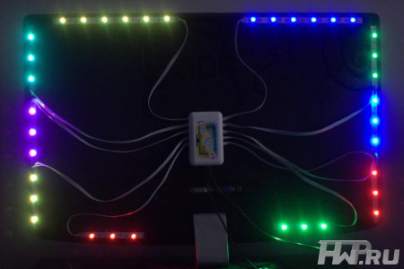
The general connection diagram is as follows (the diagram shows the power connection for my version):

Power is supplied to the tape from both ends - two parallel connections. For example, if I made the backlight on all 4 sides, and the tape was 60 LEDs per meter (i.e., the maximum power is 54 W), then I would make the following power supply:

The supply wires must be used appropriate, the smaller the gauge (AWG), the better, so that they are more than enough for the calculated current strength.
There are two pins going to the Arduino from the tape. GND, which needs to be connected to the corresponding pin on the Arduino. And DATA, which needs to be connected to the sixth digital pin through a 300-550 Ohm resistor (preferably 470 Ohm). If you do not have a resistor, then in most cases everything will work fine without it, but it is better to have one. A resistor can be bought for a couple of kopecks at any radio store. The Arduino microcomputer itself can be placed in any convenient case, many use the Kinder surprise egg for this. The Arduino should be placed as close to the tape as possible so that the DATA leads are as short as possible.
Soldering wires to tape is simple. The main rule is that the time of contact with the soldering iron should be minimal; you cannot "poke around" with a soldering iron.
In my case, it turned out like this:


Two black high-quality USB cables went for power, and a white one for connecting to a computer. I ran out of white heat shrink tubing, I used red ones. Not so “pretty”, but it suits me (it's still hidden behind TV).
An important question is how to bend the tape at right angles? If you have a 60 LED strip, then the strip needs to be cut and connected with short wires (placing all this in a heat shrink tube). You can buy special angled connectors for three pins for LED strips (4 pins in the picture, just for example):

If you have a 30 LED strip, then the distance between the LEDs is large, you can easily make a corner without cutting. Remove a piece of "silicone" coating, isolate (you can even use "tape") the contact pad and bend it according to the scheme:
I cut off a piece of tape to practice. The main thing is not to overdo it - they were slightly bent once and that's it. You do not need to bend here and there, you do not need to squeeze the bend line strongly.

Here is the rear view of the TV, all the wires go through the hole into the cabinet:

Software part
This is the simplest.We connect the Arduino microcomputer via USB. Driver ( serial interface CH340) will install automatically. If this did not happen, then in the Arduino IDE folder there is a Drivers folder with everything you need.
Launch Arduino IDE and open the Adalight.ino file.

We change the number of LEDs in the code. I have 57.

Tools\u003e Board\u003e Arduino nano
Tools\u003e Port\u003e Select COM port (there will be the desired option)
Press the button "Download":

The program will inform you when the download is complete (this is literally a couple of seconds).
Done. You need to disconnect the Arduino from USB and reconnect. The ribbon will light up sequentially in red, green and blue - the Arduino has activated and is ready to work.
Download and install the program. In the program, click "More settings" and specify the device - Adalight, COM port and the number of LEDs. Select the number of frames to capture (up to 60).

Next, click Show Capture Zones\u003e Zone Configuration Wizard. Select your ribbon configuration.

Click Apply and Save Settings. This concludes the basic settings. Then you can experiment with the size of the capture zones, color correction of the tape, etc. The program has many different settings.

To activate a profile, just double-click on the corresponding icon (AmbiBox profiles) in the Windows notification area. The tape will immediately light up. It also turns off by double clicking.
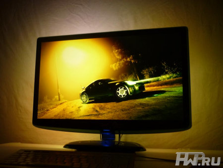
That's basically it. You saw the result at the beginning of the article. Nothing complicated, cheap and great. I'm sure you will do better, so share your crafts in the comments.
You've probably seen modern TVs with dynamic backlighting called Ambilight from Philips. The essence of her work is to highlight the space behind the TV with different color combinations, depending on the events taking place on the screen. However, for the purchase of such a TV, you need to pay tens of thousands of rubles, so it is not available to everyone.
At the same time, fans of watching movies on the monitor screen and fans of computer games do not need Philips Ambilight TVs.
PaintPack vs Ambilight. Ours are winning!
What should ordinary computer scientists do, who also want to bring an amazing play of light into the surrounding space, magically beating out of the monitor? We present you a new development called PaintPack. This module is designed to implement the same idea as Ambilight technology, but allows you to achieve the "light around" any computer monitor, and not the purposefully purchased large TV for this.

A device called PaintPack in a simpler design is a small box with ten ribbon cables with bright LEDs at the ends. These LEDs are evenly spaced around the perimeter of the back of the monitor to provide an even backlight according to what is happening on the screen. The second more advanced version of the Russian analogue of Ambilight is the PaintPack light strip with 30 LEDs, connected in separate blocks of several pieces for convenient placement on the monitor and creating brighter and more detailed backlighting.

This is many times lower than the price of TVs with Ambilight, and at the same time you are buying a device that can be easily removed and connected to different monitors, depending on the need.
PaintPack - for beginner and professional
Using the PaintPack module presents no difficulties even for a person with minimal computer training. In order for the device to work and immerse you in a world of new visual sensations when watching movies or playing your favorite toys, just place the LEDs on the back of the monitor, connect the module to one of the USB connectors and install the included software.
For fixing the LEDs, the manufacturer has carefully provided special Velcro made of double-sided tape. The program for controlling the backlight of the monitor can be downloaded for free from the seller's website paintpack.ru. Here you will also find detailed instructions on what and in what sequence must be done for the correct installation and setup of the device.

Thus, every beginner can connect and configure the PaintPack module who at least once installed the program on his own and knows the location of the USB connector on his computer.
A person who is well acquainted with a computer and its accompanying peripheral devices will certainly like the PaintPack module for its wide possibilities for self-tuning to individual needs.
A quick guide to installing and setting up the PaintPack module
The PaintPack module is provided with a special application that can be downloaded for free on the manufacturer's website. The program is periodically updated when new features are added to it.

After the program has successfully installed, you need to attach the device case to the back of the monitor, approximately in its center. Then the LEDs are glued, they can be arranged in any order at your discretion or depending on the availability of free space. The main condition for placing LEDs is their uniform distribution along the perimeter of the monitor case and their location at a distance of 15-30 centimeters from the wall. Then you can start the program, turn off the lights and enjoy the magnificent light show.

For most users, the default software settings that were initially set by the manufacturer will be sufficient. If you still want to do fine tuning of the LEDs, then for this you need to run the previously installed program. In the program window, select the item with the settings and see the capture areas for different LEDs on the monitor. You can set each LED to be white or display different colors depending on what is happening on the screen. You can also turn off individual LEDs by simply unchecking the checkbox. This completes the setup, you can test the work of the backlight and then enjoy it when watching movies or clips, while playing games and other computer entertainment.

Various special effects from movies and clips, for example, explosions or dynamic chases, look especially beautiful when using the PaintPack module.
PaintPack is a great gift
We all know how difficult it is to choose gifts for loved ones several times a year. In such situations, manufacturers who release completely new things are great help. PaintPack is one great example of such a gift. The backlight module is a unique device of its kind. You will probably be surprised that the release of such affordable and versatile Ambilight analogs has not yet been mastered in any technically developed country in the world.

Even in numerous Chinese electronics factories, devices like the PaintPack are not yet produced. Therefore, if you are choosing a gift for an advanced computer user, then the PaintPack module will certainly be a pleasant surprise for him, the existence of which he did not know. This gift will be no less pleasant for a child, girlfriend and even your parents, who will surely appreciate the beautiful backlighting of the space behind the monitor.
PaintPack official website -www.paintpack.ru
Roman aka Paintpack
19/12.2011
TVs with dynamic backlighting around the display frame is one of the proprietary chips of Philips. And unlike many others, it works. Everything comes at a price, however, and TVs with Ambilight and immersive presence are more expensive than many others.
Russian developers have proposed a method that will equip monitors from any manufacturer with dynamic backlighting. To do this, you don't even have to take the device to a service center: it only takes a little time and perseverance.
In general, such a backlight can be purchased as radio components and configured independently. But, as practice shows, this is almost comparable to the ready-made options from PaintPack.
There are two main models available: a monitor version (30 LEDs) and a TV version (60 LEDs). There is also a very simple one - for 10 LEDs, but it is suitable only for the smallest monitors.
The TV version is equipped with an external power supply. Also, a larger number of LEDs speaks in its favor, which gives a larger illumination area (it will glow wider and higher, in other words). If such options are not suitable for any reason, you can contact the developers: for a small surcharge, they will offer a modified version.
mindrunway.ruPaintPack, in fact, is a small case, to which removable LED strips are connected from both sides. The box with the filling carries indicators and a power connector, as well as a microUSB for connecting to a PC. There is also a master connector (proprietary) for daisy chaining two devices.
The device body is located on the back of the TV or monitor. Then LED strips are laid in accordance with the instructions, power is connected and witchcraft begins. When connecting PaintPack to a computer via USB, you need to install drivers and configure the device in the bundled program.
 mysku.ru
 The setting is done using the AmbiBox package. It is necessary to go to the "Intelligent backlight" menu, select the screen capture method and one of the operating modes offered in the program:
- Static background - any color can be set, LED glow is regulated.
- Color music - the backlight will flash to the beat of the music. The backlight color is set to green-yellow.
- Dynamic background - smooth flow of one color into another.
- Screen capture is the main mode of operation.
In this mode, it is possible to capture color from the movies and games being watched. The backlight color will change in accordance with the image on the screen, dividing into top, bottom and side zones (each separately).
PaintPack is a bit slower than the official Philips counterpart. But taking into account the difference in cost and the possibility of upgrading any device, the choice is obvious.
A campaign to raise money for the production of Lightpack 2. This is an LED strip that hides behind a TV, receives a signal via HDMI and illuminates what is happening on the screen with appropriate colors. Sounds like Philips Ambilight, but being a standalone device has its own differences.
First, Lightpack 2 has a Lightbridge switch, which serves as a hub for HDMI devices: the tape connects to the Lightbridge, it connects to the TV, and sources are connected directly to it through four HDMI inputs.
Secondly, complete with the device, you can order “pixels” - small flashlights, which, according to the company, intensify the process of “immersion” when viewing with their flickering.
Thirdly, Lightpack 2 works with both TVs and monitors (the previous version, Lightpack without an index, was designed exclusively for computers), and you just need to plug it in to get started.
Fourth, the novelty can be used as a cozy lamp by adjusting the lighting using the app for mobile devices with the TV off.
The kit comes with SmartCorners devices, which, as the name implies, are attached at the corners and allow the device to determine the screen diagonal. The process looks like this: cut off pieces of the correct size from a roll of LED strip, fix them on the back of the TV, install SmartCorners and start watching.
Each “pixel” has a 3 Ah battery, which allows it to live for weeks without recharging. You can place it anywhere: on the wall, on the table, on the ceiling. The “pixels” are connected to the main device via Bluetooth and work both in joint mode with Lightpack 2, and separately.
Lightbridge Switch
For $ 39 you can get 1 “pixel”, for $ 179 you can get a Lightpack 2, five meters of LED strip, a set of SmartCorners and a control panel. An additional $ 80 will add five “pixels” to this kit, and a set with ten small “pixels” and one large one will cost $ 499.
The developers promise to distribute devices around the world from February next year. There is no doubt about the success of the campaign: the project takes two days, and the planned amount of $ 198,000 has already been practically collected.
 Single Big Pixel Light
  Mobile app to manage Lightpack
 Today I will tell and show you how to make dynamic monitor backlighting.
Surely you know that sitting at a computer at night is harmful to the eyes, and this is due to the contrasting line between the monitor and the darkness. Therefore, backlighting is needed to reduce eye strain. Of course, you can get by with a table lamp, but to create more comfort, well, or just for beauty.

For dynamic highlighting we need:
1) Addressable LED strip.
2) Resistor from 200-500 ohms.
3) Arduino.
4) Thick and thin wire.
5) Solder.
6) Soldering iron.
7) Flux.
8) Insulating tape
9) Nippers

Build and setup:
1) We will connect everything as in the diagram below. The scheme itself is outrageously simple. The tape is connected from a 5V power supply (the author of this homemade product will connect it to the computer's power supply), the ground of the tape and the DI contact are connected to the arduino, and the DI contact is through a resistor, that's it. Thus, the tape is powered from the computer's power supply, and the arduino from the computer's USB and via USB receives information for the LED strip.

2) First, take a thick wire that will go to the power supply and thin for the arduino, clean it, tinker and solder everything as in the photo below.

3) Next, we solder two thin wires to the arduino, not forgetting the resistor.

4) Now the fun part, you need to fix the tape on the monitor. The number of LEDs on the left and right should be the same, for example, twenty on the left and twenty on the right, the same above and below, for example, thirty above and thirty below, this is very important.

5) Lay out the ribbon on the table. A rectangle with the required length and width and with the required number of LEDs as in the photo below. Note that the beginning of the tape with the DI pin is in the lower left corner and the end of the tape is also in the lower left corner, this is also very important.

6) Well, we glue the tape to the monitor and the arduino to two-sided tape.

7) Now we connect power to the tape and the arduino via USB to the computer.
8) We flash the arduino. You can look at the firmware and instructions on how to do this.

9) Next, open the firmware file. We look where you connected the arduino and remember, then go to the "tools" and look for the "port" and select the USB port to which you connected the arduino and select it. In our case, this is port number five.

10) Then, in the first setting (highlighted in yellow, in the photo below) we indicate our number of LEDs. And we complete the firmware.

11) Now we install the AmbiBox program, it will be in the archive with the firmware. Everything is simple there. But at the end, when choosing a device, you need to specify "Adalight".

12) Launch. Immediately we put the Russian language. And automatically turn on when the computer starts up, so that this program does not interfere with the computer startup, we set a delay of 20 seconds.

13) And now go to the next tab and immediately click on "more settings".

14) Do not get scared and remember the number of the USB port to which the arduino is connected and select the desired port.

15) Next, in the program, we can select the mode of capturing color from the screen. Only the first six work for the author, but you can poke it yourself and choose the mode that suits you or just works. The author chose the "GDI FS Aero" mode. The distinctive feature of this mode is that the backlight will display standard transparent windows.

16) Press "show capture zones" and see that they are not configured at all. First, select the number of your LEDs.

17) The program should restart. Then click on the Zone Configuration Wizard. And we will adjust your parameters into the program, you can see an example in the photo below. I also advise you to increase the color picking zones, so the result will be prettier.
- The center of gravity of a rigid body and methods for finding its position Determining the coordinates of the center of gravity of a rigid body
- Determination of the moment of inertia
- Distribution law of a discrete random variable
- Simpson's method for computation
- The formula for the numerical integration of the simpson method has the form
- Continuity of a function of two variables Determining the continuity of a function of two variables at a point
- Graphical determination of stresses using a pore circle Graphical representation of a plane stress state Stress circle