Scheme of daylight fluorescent lamps. The main features of fluorescent lamp connection diagrams

 Live Journal
 Facebook
 Twitter
Lamps daylight from the very first releases and partially still ignite with the help of electromagnetic ballasts - EMPRA. The classic version of the lamp is made in the form of a sealed glass tube with pins at the ends.
What do fluorescent lamps look like?
Inside it is filled with an inert gas with mercury vapor. Its installation is carried out in cartridges through which voltage is applied to the electrodes. An electric discharge is created between them, causing an ultraviolet glow, which acts on a layer of phosphor deposited on the inner surface of the glass tube. The result is a bright glow. Switching scheme fluorescent lamps(LL) is provided by two main elements: an electromagnetic ballast L1 and a glow discharge lamp SF1.
LL switching circuit with electromagnetic choke and starter
Ignition circuits with EMPRA
A device with a throttle and a starter works according to the following principle:
- Applying voltage to the electrodes. The current through the gas medium of the lamp at first does not pass due to its high resistance. It enters through the starter (St) (fig. below), in which a glow discharge is formed. In this case, a current passes through the spirals of the electrodes (2) and begins to heat them.
- The starter contacts warm up, and one of them closes, since it is made of bimetal. The current passes through them, and the discharge stops.
- The starter contacts stop warming up, and after cooling, the bimetallic contact opens again. In the throttle (D), a voltage pulse arises due to self-induction, which is sufficient to ignite the LL.
- A current passes through the gaseous medium of the lamp; after starting the lamp, it decreases along with the voltage drop across the inductor. The starter remains disabled, since this current is not enough to start it.

Fluorescent lamp switching circuit
Capacitors (C 1) and (C 2) in the circuit are designed to reduce the level of interference. Capacitance (C 1), connected in parallel with the lamp, helps to reduce the amplitude of the voltage pulse and increase its duration. As a result, the service life of the starter and LL is increased. The capacitor (C 2) at the input provides a significant reduction in the reactive component of the load (cos φ increases from 0.6 to 0.9).
If you know how to connect a fluorescent lamp with burnt out filaments, it can be used in the CMP circuit after a slight change in the circuit itself. To do this, the coils are short-circuited and a capacitor is connected in series to the starter. According to this scheme, the light source will be able to work for some more time.
A widely used method of switching on with one throttle and two fluorescent lamps.

Switching on two fluorescent lamps with a common choke
2 lamps are connected in series with each other and the inductor. Each of them requires the installation of a starter connected in parallel. For this, one output pin is used from the ends of the lamp.
For LL, it is necessary to use special switches so that their contacts do not stick from high inrush current.
Ignition without electromagnetic ballast
To extend the life of burned-out fluorescent lamps, you can install one of the switching circuits without a choke and starter. For this, voltage multipliers are used.

Scheme for switching on fluorescent lamps without a choke
The filaments are short-circuited and voltage is applied to the circuit. After straightening, it increases by 2 times, and this is enough for the lamp to light up. Capacitors (C 1), (C 2) are selected for a voltage of 600 V, and (C 3), (C 4) - for 1000 V.
The method is also suitable for serviceable LLs, but they should not work with DC power. After some time, mercury collects around one of the electrodes, and the brightness of the glow decreases. To restore it, you need to turn the lamp over, thereby changing the polarity.
Connection without starter
The use of a starter increases the warm-up time of the lamp. At the same time, its service life is short. Electrodes can be heated without it if secondary transformer windings are installed for this.

Wiring diagram for a fluorescent lamp without a starter
Where a starter is not used, the lamp has a quick start designation - RS. If you install such a lamp with a starter start, it can quickly burn out the spirals, since they have a longer warm-up time.
Electronic ballast
The electronic control circuit of the electronic ballast has replaced the old sources of daylight to eliminate their inherent shortcomings. The electromagnetic ballast consumes excess energy, often makes noise, fails and at the same time spoils the lamp. In addition, the luminaires flicker due to the low frequency of the supply voltage.
Electronic ballast is an electronic unit that takes up little space. Fluorescent luminaires start quickly and easily, without creating noise and providing uniform illumination. The circuit provides several ways to protect the lamp, which increases the service life and makes it safer to work.
The electronic ballast works as follows:
- Heating of LL electrodes. Startup is fast and smooth, extending lamp life.
- Ignition - generating a high voltage pulse that breaks through the gas in the flask.
- Combustion - maintaining a small voltage on the electrodes of the lamp, which is sufficient for a stable process.

Electronic choke circuit
First, the alternating voltage is rectified using a diode bridge and smoothed out by a capacitor (C 2). Next, a half-bridge high-frequency voltage generator on two transistors is installed. The load is toroidal transformer with windings (W1), (W2), (W3), two of them are connected in antiphase. They alternately open the transistor switches. The third winding (W3) supplies the resonant voltage to the LL.
A capacitor (C 4) is connected in parallel with the lamp. The resonant voltage is applied to the electrodes and breaks through the gaseous medium. By this time, the filaments have already warmed up. After ignition, the resistance of the lamp drops sharply, causing the voltage to drop to a sufficient value to keep the lamp burning. The startup process takes less than 1 s.
Electronic circuits have the following advantages:
- start with any given time delay;
- installation of a starter and a massive throttle is not required;
- the lamp does not blink and does not buzz;
- high-quality light output;
- device compactness.
The use of electronic ballasts makes it possible to install it in the lamp base, which was also reduced to the size of an incandescent lamp. This gave rise to new energy-saving lamps that can be screwed into a regular standard socket.
During operation, fluorescent lamps age and require an increase in operating voltage. In the EMP circuit, the ignition voltage of the glow discharge at the starter is reduced. In this case, an opening of its electrodes may occur, which will cause the starter to operate and turn off the LL. After that it starts up again. Such a flashing of the lamp leads to its failure along with the throttle. In the electronic ballast circuit, this phenomenon does not occur, since the electronic ballast automatically adjusts to changes in the parameters of the lamp, choosing a favorable mode for it.
Lamp repair. Video
Tips for repairing a fluorescent lamp can be obtained from this video.
LL devices and circuits for their inclusion are constantly evolving in the direction of improvement specifications. It is important to be able to choose the right models and operate them correctly.
There are two ways to connect fluorescent lamps: using a starter and choke (EMPR) and using an electronic starting device (EPRA). It cannot be said that they differ fundamentally, but various devices are involved in the connection schemes.
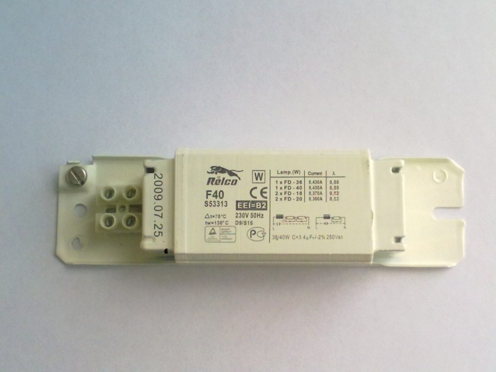
Connection diagrams for fluorescent lamps using EMPRA
EMPRA is electromagnetic ballast, and in fact, a conventional choke. In the EMPR connection scheme, a starter is necessarily used, which creates the first pulse to start the glow of the fluorescent lamp.
Wiring diagram for an EMPR fluorescent lamp
This connection scheme is used in most standard single-lamp economy class local lighting fixtures.
Circuit inductive implementation
- Supply voltage 220 Volts;
- The inductor (LL) is connected in series to the power wire and lamp terminal 1;
- The starter is connected in parallel to terminals 2 and 3 of the lamp;
- Output 4 of the lamp is connected to the second power wire;
- A capacitor is involved in the circuit, which reduces the voltage pulse, increases the life of the starter and reduces radio interference during the operation of the lamp.
Scheme inductive-capacitive implementation
The second connection scheme is called inductive-capacitive. In it, the inductor and capacitor (inductive and capacitive resistance of the circuit) are connected in series. The starter is still connected in parallel with the output of 2-3 lamps.
Wiring diagram for 2 fluorescent lamps up to 18 W (EMPR)
The connection diagrams change somewhat with two lamps. The two most common circuits are for lamps up to 18 W (series) and lamps 36 W (parallel).
In the first circuit, two starters are still involved, one starter for each lamp. The inductor is connected, as in a circuit with an inductive implementation. The power of the inductor is selected by summing the power of the lamps.
Important! In this (serial) circuit, it is necessary to use starters for 127 (110-130) Volts. The power of the lamps cannot be more than 22 watts.
In the second parallel circuit, two chokes are already involved (LL1 and LL2). There are still two starters, one starter for each lamp.
Important! This circuit uses starters for 220-240 volts. Lamp power up to 80 watts.
An important note. Modern EMPRA are produced in a single package. For connection on the case there are only contact leads. The connection diagram of the lamps is indicated on the body.
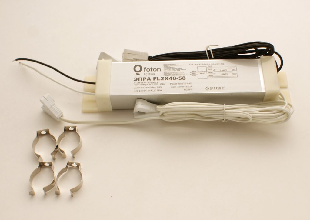
Connection diagrams for fluorescent lamps using electronic ballasts
Electronic ballast is electronic control gear. In fact, this is a complex electronic circuit that provides both start-up and stable operation (of lamps).
I note that each manufacturer of electronic ballasts in their own way displays contacts for connecting lamps to them. The connection diagram for fluorescent lamps is indicated on the body or in the electronic ballast passport. Example in the photo.
For information, I publish a selection of schemes for connecting various lamps to electronic ballasts of various markings.
Schemes for connecting compact fluorescent lamps to non-adjustable electronic ballasts (OSRAM), QT-ECO brands
Connection diagrams for unregulated electronic ballasts QTP-DL, QTP-D / L, QTP-DVE, lamps 2x55, 1x10-13, 2x16-42.
Wiring diagrams for unregulated electronic ballasts QTP5 lamps 2x14-35W, 2x24-39W, 2x54W, 1x14-35W, 1x24-39W, 1x54W, 1x80.
Wiring diagrams for electronic ballasts QT-FQ, QT-FC lamps T5 (tubular)

Conventional incandescent lamps are inefficient - they emit more heat than light. Yes, they have a short lifespan. Connecting fluorescent lamps allows you to save almost 3 times on electricity bills. Plus, such light sources have a greater range of colors and are less harmful to the eyes. However, their installation requires the purchase of special devices: chokes or electronic ballast boards.
Features of fluorescent lamps
Read also:

To understand how fluorescent lamps are connected, you need to understand the principle of their operation. Outwardly, they look like glass cylinders, the air in which is completely replaced by an inert gas under slight pressure. There is also a small amount of mercury vapor that can accelerate ionization - the movement of electrons.
Electrodes are located on both sides of the cylinder. Between them is a tungsten spiral coated with oxides of substances that, when passing current and heating, can easily move over fairly long distances, creating ultraviolet radiation (UV).
But, since this type of radiation is invisible, it is converted using a phosphor (a special composition based on calcium halophosphate, which coats the walls of the cylinder), capable of absorbing UV, in return emitting visible rays of light. The color of illumination depends on the type of phosphor.
After turning on the device and switching to the working state, the current strength in it can increase due to the drop in gas resistance. If you do not limit this process, it can quickly burn out.
To reduce the current strength, chokes (limiters) are used - helical inductors that give an additional load and are able to shift the phase of the alternating current and maintain the desired power for the entire period of switching on. Restrictive devices have another name: ballasts or ballasts (ballasts).
Read also:
More advanced types of ballast are electronic mechanisms (electronic ballasts), the principle of operation of which will be described in the next chapter. To start the discharge, a starting device called a starter is used. .
An electromagnetic choke or electronic ballast should be selected depending on the number of lamps and their power. It is forbidden to connect a device designed for two lamps to one. In order to avoid the failure of the device, it is also not necessary to connect the electronic ballast without a load, that is, lamps.
Operating principle
Read also: Installing a gas boiler in a private house: all the necessary requirements for a quick and legal launch of the heating system (Photo & Video) + Reviews

The principle of operation of fluorescent lamps
Let us briefly describe the interaction scheme of the starter, ballast and lamp:
- When power is applied, the current passing through the control gear passes through the starter contacts along the tungsten spirals, heating them up and then goes towards zero
- The starter is equipped with a pair of contacts: movable and fixed. When current is applied, the movable contact (bimetallic), heating up, changes its shape and connects to the first
- In this case, the current strength immediately increases significantly to the limit limited by the throttle. The electrodes heat up
- The starter plate, on the contrary, begins to cool and disconnects the contacts. At this moment, there is a sharp jump in voltage and a breakdown of the gas by electrons. When mercury turns into vapor, the light source switches to operating mode
- The starter is no longer involved in the process - its contacts are open.
Basic connection steps
Read also:

The wiring diagram for a fluorescent lamp with a choke is quite simple:
- The inclusion of a compensating capacitor in the circuit allows you to reduce energy losses and save its consumption. In principle, the system will work without it, but with high energy costs.
- The voltage must pass sequentially through all points, starting with the capacitor
- Next, the PRA is included in the system. To obtain an even glow, its parameters must ideally match the lamp power
- The choke is connected to the light source in series
- After it leaves the coil, connect the starter terminals
- We mount a second network contact to it
Unfortunately, the starter is not a very reliable device. Plus, during operation, the lamp may flicker, negatively affecting vision. In principle, it is possible to connect without it. You can replace this part with a spring-loaded button-switch.
Installation of two lamps
Read also:

No matter how many light sources are required to be included in the lighting system, they are all connected in series. Two starters are required to start two lamps, respectively. They are connected in parallel.
So, let's describe the process of connecting 2 fluorescent lamps at once:
- The phase must first approach the inductor input
- From him it should go to the first lamp
- Then head to the first starter
- Then go to the second contact pair of the same light source
- The output contact is connected to zero
- The second pipe is connected in exactly the same sequence. The first is PRA. Then the contact of the second light source, and so on.
If you understand the principle of this circuit, you can easily connect 3 or 4 fluorescent lamps in the same way.
Pair of lamps and one choke
Read also:

Two starters are needed here, but an expensive ballast can be used alone. The connection diagram in this case will be a little more complicated:
- We connect the wire from the starter holder to one of the light source connectors
- The second wire (it will be longer) should run from the second starter holder to the other end of the light source (bulb). Please note that it has two nests on both sides. Both wires must go into parallel (identical) sockets located on the same side.
- We take the wire and insert it first into the free socket of the first and then the second lamp
- In the second socket of the first we connect the wire with the socket connected to it
- We connect the bifurcated second end of this wire to the choke
- It remains to connect a second light source to the next starter. We connect the wire to the free hole in the socket of the second lamp
- With the last wire we connect the opposite side of the second light source to the throttle
Connection without choke
Read also:Infrared ceiling heater with thermostat - modern technologies in your home (Prices) + Reviews

This method is mainly used in older lamps when the ballast fails. This can be done by using direct current, the value of which is higher than usual. That is, the voltage at the time of start-up should be increased. The strength of this voltage is selected based on the characteristics of both the network and the light source itself.
To connect a fluorescent lamp without a choke, a diode bridge (or a pair of diodes) must be connected. Contacts are closed on both sides in pairs. On one side of the light source should be plus, on the other minus.
A similar scheme can be used even with a burnt filament. After all, a cylinder with gas with this method will be fed by a constant voltage. Just keep in mind that this method can be used for a short period - over time, the pipe will quickly darken, and then, due to the burnout of the phosphor, it will completely stop emitting light.
ECG connection
Read also:

Chokes are quite noisy devices. Therefore, their last years connected to the fluorescent lighting system infrequently, replacing them with electronic ballasts, digital or analog.
Such devices no longer need a starter. Essentially, electronic triggers are small electronic boards. They themselves are able to regulate the voltage level and provide an even light, without flicker. Plus, they are safer and less flammable in operation and have a longer service life.
There can be many options for implementing electronic ballasts, but there are two main ways to start:
- sources are preheated; this helps to increase the efficiency of the device and reduce its flicker
- using an oscillatory circuit; the filament in this case is part of it; when the discharge passes, the circuit parameters change, as a result, the voltage drops to the required level
You can get rid of annoying buzzing and blinking by replacing the old throttle with a modern electronic ballast. For this you should:
- Disassemble the old circuit by removing the throttle, starter, and condensate from it. Only a light source and wires should remain inside
- We attach the electronic ballast selected for power to the body with self-tapping screws. If there are two lamps, then the power of the electronic mechanism should be 2 times higher
- We connect it with wires to the sockets of the lamps
- If the assembly is done correctly, both light sources should light up at the same time, evenly. bright light. Buzz, of course, should no longer be.
A fluorescent lamp (LL) is a light source created by an electric discharge in an environment of mercury vapor and an inert gas. In this case, an invisible ultraviolet glow appears, which acts on the phosphor layer deposited on the inside of the glass flask. A typical circuit for switching on a fluorescent lamp is a ballast with an electromagnetic ballast (EMPRA).
Device and description LL
The bulb of most lamps has always had a cylindrical shape, but now it can be in the form of a complex figure. At the ends, electrodes are mounted in it, structurally similar to some incandescent lamp filaments made of tungsten. They are soldered to external pins that are energized.
The gas electrically conductive medium inside the LL has a negative resistance. It manifests itself in a decrease in voltage between opposite electrodes with an increase in current, which must be limited. The circuit for switching on a fluorescent lamp contains a ballast (choke), the main purpose of which is to create a large voltage pulse for its ignition. In addition to it, the EMPRA includes a starter - a glow discharge lamp with two electrodes placed inside it in an inert gas environment. One of them is made of In the initial state, the electrodes are open.

The principle of operation of LL
The starter circuit for switching on fluorescent lamps works as follows.
- Voltage is applied to the circuit, but at first no current flows through the LL due to the high resistance of the medium. Current passes through the spirals of the cathodes and heats them up. In addition, it also enters the starter, for which the supplied voltage is sufficient for a glow discharge to occur inside.
- When the starter contacts are heated from the passing current, the bimetallic plate closes. After that, the metal becomes a conductor, and the discharge stops.
- The bimetallic electrode cools down and opens the contact. In this case, the inductor gives out a high voltage pulse due to self-induction, and the LL ignites.
- A current flows through the lamp, which then decreases by a factor of 2, since the voltage across the inductor drops. It is not enough to restart the starter, the contacts of which remain open when the LL burns.
The switching circuit of two installed in one lamp provides for the use of one common choke for them. They are connected in series, but each lamp has one parallel starter.

The disadvantage of the lamp is to turn off the second lamp if one of them is out of order.
Important! With fluorescent lamps, special switches must be used. For budget devices, the starting currents are large, and the contacts can stick.
Throttless inclusion of fluorescent lamps: schemes
Despite the low cost, electromagnetic ballasts have disadvantages. They were the reason for the creation of electronic ignition circuits (electronic ballasts).
How LL starts with electronic ballast
Throttless switching on of fluorescent lamps is carried out through an electronic unit, in which a sequential change in voltage is formed when they are ignited.

Advantages of the electronic launch circuit:
- the ability to start with any time delay;
- no need for a massive electromagnetic choke and starter;
- lack of buzzing and blinking of lamps;
- high light output;
- lightness and compactness of the device;
- longer service life.
Modern electronic ballasts are compact and have low power consumption. They are called drivers, placing them in the base of a small-sized lamp. The chokeless switching of fluorescent lamps allows the use of conventional standard lampholders.
The electronic ballast system converts the mains alternating voltage into high frequency. First, the LL electrodes are heated, and then a high voltage is applied. At high frequency efficiency increases and flicker is completely eliminated. The switching circuit can provide or with a smooth increase in brightness. In the first case, the service life of the electrodes is significantly reduced.
Overvoltage in electronic circuit is created through an oscillatory circuit, leading to resonance and ignition of the lamp. Starting is much easier than in the classical circuit with an electromagnetic choke. Then the voltage is also reduced to required value hold the discharge.

The voltage is rectified after which it is smoothed by a parallel-connected capacitor C 1. After connecting to the network, the capacitor C 4 is immediately charged and the dinistor breaks through. A half-bridge generator is started on the transformer TR 1 and transistors T 1 and T 2. When a frequency of 45-50 kHz is reached, a resonance is created using a series circuit C 2 , C 3 , L 1 connected to the electrodes, and the lamp lights up. This circuit also has a choke, but with very small dimensions, allowing it to be placed in the lamp base.
The electronic ballast has automatic adjustment to the LL as the characteristics change. After a while, a worn-out lamp requires a boost in voltage to ignite. In the EMPRA circuit, it simply will not start, and the electronic ballast adjusts to the change in characteristics and thus allows the device to be operated in favorable modes.
The advantages of modern electronic ballasts are as follows:
- smooth start;
- economy of work;
- preservation of electrodes;
- flicker elimination;
- performance at low temperatures;
- compactness;
- durability.
The disadvantages are higher cost and complicated ignition scheme.
Application of voltage multipliers
The method makes it possible to turn on the LL without an electromagnetic ballast, but is mainly used to extend the life of the lamps. The circuit for switching on burned-out fluorescent lamps allows them to work for some more time if the power does not exceed 20-40 watts. In this case, the filaments can be both intact and burned out. In both cases, the leads of each filament must be short-circuited.

After rectification, the voltage doubles, and the lamp lights up instantly. Capacitors C 1 , C 2 are selected for an operating voltage of 600 V. Their disadvantage lies in their large dimensions. Capacitors C 3, C 4 set mica to 1000 V.
LL is not intended for direct current supply. Over time, mercury accumulates near one of the electrodes, and the glow weakens. To restore it, change the polarity by turning the lamp over. You can install a switch to keep it on.
Starterless circuit for switching on fluorescent lamps
The starter circuit requires a long warm-up of the lamp. In addition, it sometimes has to be changed. In this regard, there is another scheme with electrode heating through the secondary windings of the transformer, which also performs the function of a ballast.

When fluorescent lamps are switched on without a starter, they must have the designation RS (quick start). A lamp with a starter start will not work here, since its electrodes warm up longer and the spirals will quickly burn out.
How to turn on a burnt out lamp?
If the spirals are out of order, the LL can be ignited without a voltage multiplier, using the usual EMP circuit. The switching circuit of a burnt-out fluorescent lamp changes slightly compared to the usual one. To do this, a capacitor is connected in series to the starter, and the pins of the electrodes are short-circuited. After such a small alteration, the lamp will work for some more time.
Conclusion
The design and switching circuit of a fluorescent lamp is constantly being improved in the direction of efficiency, reduction in size and increase in service life. It is important to operate it correctly, to understand the whole variety of types produced and to know effective connection methods.
Fluorescent lamps, despite all their "survivability", compared to conventional incandescent bulbs, at one point also fail and stop shining.
Of course, their service life cannot be compared with LED models, but as it turns out, even with a serious breakdown, all these LB or LD lamps can again be restored without any serious capital costs.
First of all, you need to find out what exactly burned out:
- the fluorescent light bulb
- starter
- or choke
How to do this and quickly check all these elements, read in a separate article.

If the bulb itself burned out and you are tired of such light, then you can easily switch to LED lightening, without any major upgrade of the luminaire. And this is done in several ways.

One of the most serious problems is a failed throttle.

At the same time, most consider such a fluorescent lamp to be completely unusable and throw it away, or move it to the pantry for spare parts for the rest.
We’ll make a reservation right away that you won’t be able to start the LB lamp without a choke, simply throwing it out of the circuit and not putting something else there. The article will discuss alternative options when this very throttle can be replaced with another element that you have at hand at home.
How to start a fluorescent lamp without a choke
What do homemade and radio amateurs advise to do in such cases? They recommend using the so-called chokeless circuit for switching on fluorescent lamps.

It uses a diode bridge, capacitors, ballast resistance. Despite some advantages (the ability to start burnt-out fluorescent lamps), all these schemes are a dark forest for the average user. It is much easier for him to buy a new lamp than to solder and assemble this entire structure.

Therefore, we first consider another popular way to start LB or LD lamps with a burnt choke, which will be available to everyone. What do you need for this?
You will need an old burnt-out energy-saving light bulb with a regular E27 base.

Of course, a circuit using it cannot be considered absolutely chokeless, since a choke is still present on the energy-saving board. It's just that it is much smaller in size, since the housekeeper operates at frequencies up to several tens of kilohertz.
This mini choke limits the current through the lamp and gives high voltage impulse for ignition. In fact, this is an electronic ballast in a miniature version.

Therefore, some conscious and thrifty citizens who have not yet handed them over to special collection points keep such products on their shelves in lockers.

They change them for a reason. These light bulbs in working order are very harmful to health, both in terms of light pulsations and in relation to the emission of dangerous ultraviolet radiation.
Although ultraviolet is not always harmful. And sometimes it does us a lot of good.

At the same time, do not forget that linear luminescent models equally have the same negative factors. It is they who actively scare those who like to grow plants under the light of phytolamps.

But back to our energy savings. Most often, the luminous spiral tube stops working for them (the tightness disappears, breaks, etc.).

In this case, the circuit and the internal power supply remain safe and sound. They can be used in our business.
First, disassemble the light bulb. To do this, along the parting line, use a thin flat screwdriver to open and separate the two halves.

When separating, never hold on to the glass tubular flask.


When parsing, remember which pair is connected where. These pins can be located on one side of the board, or on different sides.

In total, you should have 4 contacts, where you should solder the wires in the future.
Well, of course, do not forget about the power supply 220V. These are the very veins that come from the base.


That is, separately two wires on the right and two wires on the left. After that, it remains only to apply a voltage of 220V to the energy-saving circuit.
The fluorescent light bulb will burn perfectly and work normally. You don't even need a starter to start. Everything connects directly.


If the starter is present in the circuit, it will have to be thrown out or shunted.
How to choose the power of an energy-saving lamp
Such a lamp starts up instantly, in contrast to the long blinks and flickers of the usual LB and LD models.

What are the disadvantages of such a connection scheme? Firstly, the operating current in energy-saving lamps at equal power is less than that of linear fluorescent lamps. What is the risk?

And the fact that by choosing a housekeeper of equal or lesser power with LB, your board will work with overload and at one fine moment will boom. To prevent this from happening, the power of boards from housekeepers should ideally be 20% more than that of fluorescent lamps.
That is, for a 36W LDS model, take a board from a 40W and higher sweetheart. And so on, depending on the proportions.

If you are converting a lamp with one inductor into two light bulbs, then consider the power of both.

Why else do you need to take it with a margin, and not select the CFL power equal to the power of fluorescent lamps? The fact is that in nameless and inexpensive CFL bulbs, the real power is always an order of magnitude less than the declared one.
Therefore, do not be surprised when, by connecting to the old Soviet lamp LB-40, a board from a Chinese housekeeper for the same 40W, you will eventually get a negative result. This is not a scheme that does not work - it is the quality of goods from the Middle Kingdom that does not correspond to the "reinforced concrete" Soviet guests.
2 circuits for chokeless switching on of fluorescent lamps
If you still intend to assemble a more complex structure, with the help of which even burned-out linear lamps are launched, then let's consider such cases.
The simplest option is a diode bridge with a pair of capacitors and an incandescent light bulb connected in series to the circuit as a ballast. Here is a diagram of such an assembly.

Its main advantage is that in this way it is possible to start the lamp not only without a choke, but also a burnt out lamp, which does not have whole spirals on the pin contacts at all.

For 18W tubes, the following components are suitable:

- capacitor 2nF (up to 1kv)
- capacitor 3nF (up to 1kv)
- incandescent bulb 40W
For 36W or 40W tubes, the capacitances should be increased. All elements are connected like this.

After that, the circuit is connected to a fluorescent lamp.

Here is another similar chokeless circuit.

Diodes are selected with a reverse voltage of at least 1kV. The current will depend on the current of the lamp (from 0.5A or more).
We light a burnt lamp
In this circuit, when the lamp burns out, the double pins at the ends close together.

The selection of components depending on the power of the lamp, do focusing on the plate below.

If the light bulb is intact, the jumpers are still installed. This does not require preheating of the spirals up to 900 degrees, as in serviceable models.
The electrons necessary for ionization break out even at room temperature, even if the coil is burned out. Everything happens due to the multiplied voltage.

The whole process looks like this:
- initially there is no discharge in the bulb
- then a multiplied voltage is applied to the ends
- the light inside due to this instantly lights up

- then the incandescent bulb lights up, which limits the maximum current with its resistance
- the flask gradually stabilizes the operating voltage and current
- the light bulb dims a little
Disadvantages of this build:
- low brightness level
- increased pulsation

And even when supplying fluorescent lamps with constant voltage, you will very often have to change the polarity at the extreme electrodes of the bulb. Simply put, before each new inclusion, turn the lamp over.
Otherwise, mercury vapor will collect only near one of the electrodes and the lamp will not last long without periodic maintenance. This phenomenon is called cataphoresis or the entrainment of mercury vapor at the cathode end of the lamp.

Where the "plus" is connected, the brightness will be less and this edge will begin to blacken much faster.
- Procedure for performing actions - Knowledge Hypermarket
- Egg four week diet
- More about the periods and aspects of the month
- Free New Year Invitation Templates Download Kindergarten Christmas Tree Invitation
- Advent and food
- April landing calendar April landing calendar
- Best Contemporary Books Most Popular Fiction