Non-contact tachometer circuit. Digital and analog homemade tachometer

 Live Journal
 Facebook
 Twitter
Most modern cars are equipped with tachometers, facilitating the correct selection of gear, which prolongs the engine life. If your car does not have such a device, then it can be made according to the proposed description.
Tachometer circuit is shown in Fig. 1. Its main feature is the use of the K1003PP1 microcircuit, designed to control a linear scale of 12 LEDs. In the standard version described in, the microcircuit provides the formation of a column of luminous LEDs, the length of which is proportional to the input voltage.
The signal, the frequency of which is proportional to the engine crankshaft speed, is taken from the contacts of the breaker or from the amplifier-shaper of the Hall sensor and is fed through the voltage divider R1R2 to the input of the Schmitt trigger DD1.1. The purpose of the trigger and capacitor SZ is to suppress bounce pulses at the output of the chopper, high-voltage surges on the winding of the ignition coil and bring the signal to standard levels of CMOS logic with a normal steepness of the edges.
click on the diagram to enlarge
Rice. 1 Tachometer circuit
The output of the Schmitt trigger triggers a waiting multivibrator on the DD2 chip. In the main position of the switch SA1 "6000" the duration of the pulses generated by the waiting multivibrator is 2.5 ms. At a rotation speed of 6000 rpm, the pulse frequency for a four-cylinder engine is 200 Hz, the repetition period is 5 ms, the duty cycle is 2. The R12C6 integrating circuit averages these pulses, and the average voltage across the capacitor C6 is about 3 V. This voltage is fed to the pin ... 17 (UBX) DD2. At a voltage of 3 V applied to the pin. 3 (UB) of this microcircuit and determining the scale of the indication, all 12 LEDs HL1 ... HL12 are turned on, forming a luminous column.
At lower engine speeds, the duty cycle of the pulses at the DD1 output increases, the average voltage across the capacitor C6 decreases in proportion to the revolutions, and the column height becomes smaller. When the engine is stopped, no LEDs are on. The "scale division" of the LED scale is 500 rpm.
It is advisable to install LEDs of different glow colors. For example, if the optimal engine operation corresponds to 2000 ... 4000 rpm, the LEDs HL1 ... HL3 can be yellow or orange ("downshift"), HL4 ... HL8 - green ("normal"), HL9 ... HL12 - red ("change to a higher gear").
To adjust the idle speed, the switch should be set to the "1200" position. In this case, the duration of the generated pulses will increase by 5 times and will be 12.5 ms, and the “scale division” will be 100 rpm.
Chips DD1 and DD2 of the tachometer are powered through an integral voltage regulator DA1. Capacitors C1 and C2 ensure the stability of the stabilizer.
The current through the LEDs connected to the DA2 microcircuit is determined by the voltage at its pin. 2. In the daytime, when the instrument panel illumination lamps are off, a log is present at the inputs of the DD1.2 element. 0, at the output - voltage 6 V, at the pin. 2 DA2 - about 0.85 V, which sets the current to 25 mA through each LED. In the evening, when the backlight is turned on, the voltage on the pin. 2 decreases to 0.4 V, which reduces the current through the LEDs to 8 mA and, accordingly, their brightness.
A drawing of the tachometer printed circuit board is shown in Fig. 2. The design uses constant resistors MLT, trimmer SPZ-19a. Capacitor C5 of type K73-17 for a voltage of 250 V, C6 - K50-16, the rest - KM-5 and KM-6. Microcircuit DA1 - any 6 V voltage regulator, for example, KR1157EN6 with any letter index, KR142EN5B (G), KR1180EN6, 78L06, 7806. Chip K561TL1 can be replaced by KR1561TL1, CD4093, CD4093B, and K1003PP1 - by UAA180 or A277.
Orange LEDs - AL307MM (yellow ones usually shine weaker than others), green with increased brightness - AL307NM6, red - AL307BM. The LED pins are bent at 90 ° with their axes parallel to the PCB. The size of the LEDs has been reduced to 5 mm with a file.
Switch SA1 is any small toggle switch, it should be installed in close proximity to the printed circuit board.
The unused inputs of the DD1 and DD2 microcircuits are connected either to the common wire or to the +6 V circuit.
Setting up the tachometer is pretty simple. First, switch SA1 is set to the position "6000", pulses of positive polarity with an amplitude of 12 V with a frequency of 200 Hz and a duty cycle close to 2 are applied to the tachometer input to simulate a connection to a chopper. If necessary, select the resistance of the resistor R8. Then the same operation is performed for the position SA1 "1200" at an input pulse frequency of 40 Hz.
LEDs can be arranged in a circular arc. In this case, the glow of one LED from the chain may be more effective. To ensure such a mode of switching on the LEDs, their anodes should be disconnected from the outputs of the DA2 microcircuit and connected to the power output (pin 18).
A simple universal tachometer on the ATtiny2313 microcontroller
This simple tachometer on ATtiny2313 can count the number of revolutions of any engine, be it multiphase, multi-stroke, etc. It can be useful in motor vehicles to display the engine speed. In this case, it does not matter at all how many strokes or cylinders the engine has. It can also be used in conjunction with electronic motor controllers, whether single or three phase.
The tachometer circuit is very simple - one ATtiny2313 microcontroller and a four-character LED indicator. For the sake of simplicity, there are no transistor switches. The indicator can be used both with a common cathode and with a common anode - this is selected in the source. The tachometer can count revolutions both per second and per minute, which makes it completely versatile.
Additionally, the device has the ability to programmatically control the brightness: normal and reduced. If the jumper is open, the normal brightness is set. When the contacts are closed, the brightness decreases.

Click to enlarge
Let's go directly to the diagram. If the device is connected directly to a TTL motor controller, then the pulses can simply be applied to pin 6 of the microcontroller. Otherwise, you should perform the simplest level converter on a transistor.
To obtain and stabilize the supply voltage of +5 volts, a linear stabilizer 1117 with a low voltage drop was used for greater efficiency.
An indicator from a microwave oven with a common anode is used as an LED indicator. Since it already contains 220 Ohm resistors, they are not provided on the printed circuit board.

There are as many as 10 jumpers on the top of the PCB, but they are very easy to install.

SMD components are installed on the reverse side: these are two 22 pF capacitors for a quartz resonator, a stabilizer microcircuit and filter capacitors.
The crystal resonator for the ATtiny2313 microcontroller can be set to 8 or 4 MHz, this is set in the source and controls the prescaler.
The display mode of revolutions - per second or per minute - is set in the same way in the source. To display the number of revolutions per minute, the calculated number of revolutions per second is simply multiplied by software by 60. There is a possibility of software rounding of the calculated values. These nuances are commented out in the source code.
When flashing the microcontroller, it is necessary to install fuses:
CKSEL1 = 0
BODLEVEL0 = 0
BODLEVER1 = 0
SPMEN = 0
The source is written in C in Codevision AVR. It was borrowed from another project - a tachometer for a three-bladed helicopter.
Briefly about the setting: it is necessary to determine in advance how many pulses per 1 revolution will be supplied to the tachometer input. For example, if their source is a three-phase motor controller on the LB11880, then it outputs by three pulse per spindle revolution. Therefore, you should specify this value in the source code.
The choice of indicator - with a common anode or with a common cathode (unnecessary value - comment out):
// # define Anode
#define Cathode
Number of tachometric impulses per 1 shaft revolution:
#define byBladeCnt 2
Selecting the frequency of the quartz resonator - 0x00 for 4MHz, 0x01 - for 8MHz:
#define Prescaler 0x01
RPM display selection:
lTmp = (62500L * 60L * (long) wFlashCnt);
To display the number of revolutions per second, you need to remove the multiplication by 60:
lTmp = (62500L * (long) wFlashCnt);
In order to disable rounding of values, you need to comment out the following lines:
If (byDisplay> 4)
{
wRpm ++;
R + = 10;
}
Since this particular design uses a very specific indicator, no PCB layout is applied.

Tachometer consists of a 4-digit LED indicator (for accurate determination of rpm) and a group LEDs located in a circle (for a visual, more visual, determination of revolutions). The indicator shows with an accuracy of 1 rpm. The LED strip consists of 32 green LEDs and 5 red LEDs located at the end of the scale or any number of red LEDs at your discretion.
32-LED circular ruler
Point or continuous display
4-digit display
Gear shift indicator LED
Output signal limiter
Measuring 0-9999 or above 10000 rpm
Two display parameters above 9999 rpm
Options for 1 rpm, 10 rpm or 100 rpm display resolution
Automatic display of brightness in low light conditions
Adjustable for 1, 2, 3, 4, 5, 6, 8, 10 and 12-cylinder 4-stroke engines and 1, 2, 3, 4, 5 and 6-cylinder 2-stroke engines
Selecting the red line
Selection of turns of light shift
Speed limiter selection
Selecting the number of red line LEDs
Selecting the refresh period of the image
Hysteresis selection for LED bar
Choice, minimum time limit
The device can be divided into two parts:
1) control board
2) display board
The control board contains the pic16F88 controller, LED power supply and control buttons. Perhaps the most interesting thing is the control buttons with which they adjust the tachometer. There are only three buttons:
S1 - installation
When configuring the device, the green LED34 (mode) and red LED35 (setting) indicate the status. 4-digit indicator with a common anode.
The device is connected to a low level or to a high signal level. A low level is understood as a connection to the car's ECU, and a high level to the ignition coil.
The MC34063 microcircuit is a DC-DC converter that operates at a frequency of 40 kHz, commutes a transistor to supply LEDs with a stabilized current.
VR1 - allows you to regulate the output voltage of the MC34063 in the range of 1.25-4V.
Inductance L1 is wound on a 28mm ferite ring with a 0.5mm wire.
LM2940CT-5 voltage stabilizer for 5V, provides power to the control circuit. M5451 microcircuits, LED driver.
Automatic brightness is realized on the LDR1 element (photoresistor), which is located on the display board. The better the illumination, the lower the LDR1 resistance. The voltage across LDR1 at high illumination is about 1V. Depending on the resistance of LDR1, different voltages are applied to transistors Q2 and Q3, which in turn control the brightness of the LEDs through the drivers. To correct for automatic brightness, an element VR6 was introduced into the circuit, which is a 50K ohm variable resistor.
The tachometer has an electronic speed limiter, limit out.
Settings:
To switch to the settings mode, you need to hold down the button up and apply power, if the up button is not pressed, then the device will go into normal operation. Release the button up and the unit should light up on the display, which means mode 1. The green "mode" LED will be on. It is necessary to select the mode from 1-13 with the buttons up and down.
In each mode, you need to make your own adjustments.
| Mode | Possible settings | Note |
| 1 Number of cylinders | 1-12 | selection of the number of cylinders |
| 2 Red LEDs | 0-10 | allows you to change the length of the display of the red line |
| 3 Red line | 0-30,000 | lighting up the first red LED |
| 4 RPM per LED | automatically | automatically calculated from modes 2 and 3 |
| 5 Light shift | 0-30,000 | if you do not need to install further than the red line |
| 6 Speed limiter | 0-30,000 | install an electronic speed limiter (see 12) |
| 7 Hysteresis | 0-255 | prevents LED flickering, see mode 4 |
| 8 Display updates | 0-510ms in 2ms steps | the display refresh period is set |
| 9 Display format | 0,1,2 | set the display format rpm 0) 9999 1) 9.999-10.00 2) 9.99-10.00 |
| 10 Resolution | 0,1,10 | set resolution 0) 1 rpm 1) 10 rpm 10) 100 rpm |
| 11 Visualization | 0 or 1 | 0) to display point 1) to display continuous change |
| 12 Sensitivity | 0 or 1 | 0) for low level "0V" 1) for high level "+ 5V" |
| 13 Chapel for the period | 0-510ms in 2ms steps | set the minimum time when the cutoff output is active |
Mode 1 - number of cylinders: enter the exact number of cylinders for a 4-stroke engine (1-12 cylinders). For example, select “2” for 1-cylinder 2-stroke, 4 for 2-cylinder 2-stroke, etc. For motorcycles, 11 or 7 are suitable for 2-cylinder asymmetric 4-stroke engines. 9 for tuning for an asymmetric 3 cylinder 4-stroke engine.
Mode 2 - red LEDs: responsible for the glow of the red LED strip, select the number of LEDs that will light up, by default 5, you can select 0-10.
Mode 3 - Red Line: This mode is used to set the maximum RPM recommended for your engine. The default is 9000. Note that 10,000 revolutions will be displayed as 10.00.
Mode 4 - RPM per LED: This mode shows the RPM gain for each LED in the bar, i.e. how many revolutions are there per LED.
Mode 5 - Light Shift: The default value is 8000 rpm, ranging from zero and above 30 thousand rpm. The setting is in x1000 format, for example 8000 is displayed as 8.00.
Mode 6 - RPM Limiter: This mode sets the RPM limitation. During operation, the output limiter changes, when the measured speed goes higher, then this parameter and the output signal level depends on the setting (see Mode 12). This setting can be changed in 100 steps from 9900 rpm in the range from zero to above 30,000 rpm.
Mode 7 - hysteresis: to avoid the threshold value, you can set hysteresis, for example, the subsequent LEDs quickly turn on and off. The default setting hysteresis is 50 rpm and can be changed in 1 from 0-255 rpm. Note that the hysteresis value must be less than the value (see mode 4).
Mode 8 - Display Updates: Refreshes every 1ms, but this is too fast for the digital display to read if there is any change in RPM. As a result of the update, the digital display will slow down to a more comfortable speed. Typically an update period of 200 ms (or five changes per second) is appropriate. The default setting is 250ms with a step of 2 from 0-510ms.
Mode 9 - Display Format: This adjustment is mainly for servicing engines that are above 10,000 rpm. An initial value of "0" sets the display to display from 0-9999 RPM. Above this figure, the display shows "0" 10000 rpm, "1000" at 11000, etc. Use this setting for engines that do not exceed 10,000 rpm, or that only occasionally reach this level.
Mode 10 - resolution: if you do not like how the readings run at a fast set of revolutions, you can lower the resolution, to lower the resolution, set "1" and the last digit will always show zero. If "2" then the last two will be zero.
Mode 11 - visualization, point or ruler: whether the LED bar will operate in point mode (i.e. the LED is on at any time) or as a continuous change. Select "0" point mode or "1" for continuous mode.
Mode 12 - sensitivity: if "0" is set, then it goes from 0 to + 5V, and if "1" then from + 5V to 0.
Mode 13 - side-limit for the period: the minimum time is set when the cutoff output is active
The tacometer has a maximum speed limiter, the output of which can be used in a separate circuit that will limit the engine speed. For example, in the ignition or fuel supply circuit.
Today you can make digital with your own hands without resorting to powerful expensive components. In this article, we will consider a similar option for a digital tachometer. In our case, the tachometer modes will be switched by a three-position switch. The tachometer will have two modes of operation, they will differ in the limits of measurements of the crankshaft speed.
In this way, we can control low rpm with higher accuracy. The information will be displayed on a display in the dashboard, consisting of a line of 12. The measuring unit is a DD1 dual flip-flop microcircuit. From the ignition coil, pulses are sent to its cells.
After that, from the terminals 1 and 13 of the trigger, the signal goes to the driver circuit of the corresponding output signals of the "Ang Out" and "Tah Out" block. The first block carries information about the time of contact closure, and the second - information about the speed.
Specifications
Supply voltage [V] ............................................. ........................ 9-18
Consumption current not more than [mA] ........................................... ......................eight
Output voltage range [V] ............................................ ........ 0-3
Range of measured revolutions [rpm]
with open contacts K1 and K2 ............................................ ..... 0-2000
with closed contacts K1 and K2 ............................................ ........ 0-6000
The range of the measured time of the closed state of the contacts
[%].................................................. ................0-100
Connection diagram to the vehicle's on-board network:
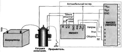
Automotive electrical measuring unit:

Measuring unit board.
Tachometer consists of a 4-digit LED indicator (for accurate determination of rpm) and a group LEDs located in a circle (for a visual, more visual, determination of revolutions). The indicator shows with an accuracy of 1 rpm. The LED strip consists of 32 green LEDs and 5 red LEDs located at the end of the scale or any number of red LEDs at your discretion.
32-LED circular ruler
Point or continuous display
4-digit display
Gear shift indicator LED
Output signal limiter
Measuring 0-9999 or above 10000 rpm
Two display parameters above 9999 rpm
Options for 1 rpm, 10 rpm or 100 rpm display resolution
Automatic display of brightness in low light conditions
Adjustable for 1, 2, 3, 4, 5, 6, 8, 10 and 12-cylinder 4-stroke engines and 1, 2, 3, 4, 5 and 6-cylinder 2-stroke engines
Selecting the red line
Selection of turns of light shift
Speed limiter selection
Selecting the number of red line LEDs
Selecting the refresh period of the image
Hysteresis selection for LED bar
Choice, minimum time limit
The device can be divided into two parts:
1) control board
2) display board
The control board contains the pic16F88 controller, LED power supply and control buttons. Perhaps the most interesting thing is the control buttons with which they adjust the tachometer. There are only three buttons:
S1 - installation
When configuring the device, the green LED34 (mode) and red LED35 (setting) indicate the status. 4-digit indicator with a common anode.
The device is connected to a low level or to a high signal level. A low level is understood as a connection to the car's ECU, and a high level to the ignition coil.
The MC34063 microcircuit is a DC-DC converter that operates at a frequency of 40 kHz, commutes a transistor to supply LEDs with a stabilized current.
VR1 - allows you to regulate the output voltage of the MC34063 in the range of 1.25-4V.
Inductance L1 is wound on a 28mm ferite ring with a 0.5mm wire.
LM2940CT-5 voltage stabilizer for 5V, provides power to the control circuit. M5451 microcircuits, LED driver.
Automatic brightness is realized on the LDR1 element (photoresistor), which is located on the display board. The better the illumination, the lower the LDR1 resistance. The voltage across LDR1 at high illumination is about 1V. Depending on the resistance of LDR1, different voltages are applied to transistors Q2 and Q3, which in turn control the brightness of the LEDs through the drivers. To correct for automatic brightness, an element VR6 was introduced into the circuit, which is a 50K ohm variable resistor.
The tachometer has an electronic speed limiter, limit out.
Settings:
To switch to the settings mode, you need to hold down the button up and apply power, if the up button is not pressed, then the device will go into normal operation. Release the button up and the unit should light up on the display, which means mode 1. The green "mode" LED will be on. It is necessary to select the mode from 1-13 with the buttons up and down.
In each mode, you need to make your own adjustments.
| Mode | Possible settings | Note |
| 1 Number of cylinders | 1-12 | selection of the number of cylinders |
| 2 Red LEDs | 0-10 | allows you to change the length of the display of the red line |
| 3 Red line | 0-30,000 | lighting up the first red LED |
| 4 RPM per LED | automatically | automatically calculated from modes 2 and 3 |
| 5 Light shift | 0-30,000 | if you do not need to install further than the red line |
| 6 Speed limiter | 0-30,000 | install an electronic speed limiter (see 12) |
| 7 Hysteresis | 0-255 | prevents LED flickering, see mode 4 |
| 8 Display updates | 0-510ms in 2ms steps | the display refresh period is set |
| 9 Display format | 0,1,2 | set the display format rpm 0) 9999 1) 9.999-10.00 2) 9.99-10.00 |
| 10 Resolution | 0,1,10 | set resolution 0) 1 rpm 1) 10 rpm 10) 100 rpm |
| 11 Visualization | 0 or 1 | 0) to display point 1) to display continuous change |
| 12 Sensitivity | 0 or 1 | 0) for low level "0V" 1) for high level "+ 5V" |
| 13 Chapel for the period | 0-510ms in 2ms steps | set the minimum time when the cutoff output is active |
Mode 1 - number of cylinders: enter the exact number of cylinders for a 4-stroke engine (1-12 cylinders). For example, select “2” for 1-cylinder 2-stroke, 4 for 2-cylinder 2-stroke, etc. For motorcycles, 11 or 7 are suitable for 2-cylinder asymmetric 4-stroke engines. 9 for tuning for an asymmetric 3 cylinder 4-stroke engine.
Mode 2 - red LEDs: responsible for the glow of the red LED strip, select the number of LEDs that will light up, by default 5, you can select 0-10.
Mode 3 - Red Line: This mode is used to set the maximum RPM recommended for your engine. The default is 9000. Note that 10,000 revolutions will be displayed as 10.00.
Mode 4 - RPM per LED: This mode shows the RPM gain for each LED in the bar, i.e. how many revolutions are there per LED.
Mode 5 - Light Shift: The default value is 8000 rpm, ranging from zero and above 30 thousand rpm. The setting is in x1000 format, for example 8000 is displayed as 8.00.
Mode 6 - RPM Limiter: This mode sets the RPM limitation. During operation, the output limiter changes, when the measured speed goes higher, then this parameter and the output signal level depends on the setting (see Mode 12). This setting can be changed in 100 steps from 9900 rpm in the range from zero to above 30,000 rpm.
Mode 7 - hysteresis: to avoid the threshold value, you can set hysteresis, for example, the subsequent LEDs quickly turn on and off. The default setting hysteresis is 50 rpm and can be changed in 1 from 0-255 rpm. Note that the hysteresis value must be less than the value (see mode 4).
Mode 8 - Display Updates: Refreshes every 1ms, but this is too fast for the digital display to read if there is any change in RPM. As a result of the update, the digital display will slow down to a more comfortable speed. Typically an update period of 200 ms (or five changes per second) is appropriate. The default setting is 250ms with a step of 2 from 0-510ms.
Mode 9 - Display Format: This adjustment is mainly for servicing engines that are above 10,000 rpm. An initial value of "0" sets the display to display from 0-9999 RPM. Above this figure, the display shows "0" 10000 rpm, "1000" at 11000, etc. Use this setting for engines that do not exceed 10,000 rpm, or that only occasionally reach this level.
Mode 10 - resolution: if you do not like how the readings run at a fast set of revolutions, you can lower the resolution, to lower the resolution, set "1" and the last digit will always show zero. If "2" then the last two will be zero.
Mode 11 - visualization, point or ruler: whether the LED bar will operate in point mode (i.e. the LED is on at any time) or as a continuous change. Select "0" point mode or "1" for continuous mode.
Mode 12 - sensitivity: if "0" is set, then it goes from 0 to + 5V, and if "1" then from + 5V to 0.
Mode 13 - side-limit for the period: the minimum time is set when the cutoff output is active
The tacometer has a maximum speed limiter, the output of which can be used in a separate circuit that will limit the engine speed. For example, in the ignition or fuel supply circuit.
- Connecting a rotary encoder to a computer via USB
- Homemade TV backlight from USB
- Evaluation of methods for measuring low frequencies on the Arduino Brief description of the frequency meter FC1100-M2
- Photoresistor and LEDs on Arduino
- Line transformer tvs
- Complementary FET Hi-Fi Amplifier
- Linear transformer tvs 90 l wiring diagram