Regulation of the pump flow by throttling. Centrifugal Pump Performance
 Live journal
 Facebook
 Twitter
For a long time, the performance of centrifugal pumps was controlled by changing the bore of the outlet pipe or by using guide vanes. At the same time, the development of finer technologies using centrifugal pumps, and the continuous increase in the price of natural and energy resources, increasingly sets the task of finding more economical methods and devices for controlling a centrifugal pump. At the same time, the use of a pump as a control object requires the reduction of a mathematical model that describes its behavior in static and dynamic modes to an understandable and convenient form for control purposes.
It is known that the internal working process in a centrifugal pump is apparently described by the equations of turbulent flow and continuity of flow. At the same time, it is impossible to establish the dependence of the parameters of the external characteristics of the pump on the flow parameters at this stage. In practice, it is often possible to observe some discrepancy between the pump behavior and generally accepted standards. This is especially evident when starting and running the pump on a back pressure system. At the same time, the classical dependencies describing its operation require adjustment. For example, it is known that the pressure at the pump outlet is proportional to the square of the speed of rotation of the impeller (n \u003d C1 ^), however, when working on a system with back pressure, the exponent can vary over a very wide range (2-10). Or at start-up, the pressure at the pump outlet appears only after the impeller speed reaches certain values, that is, some time passes from the moment the rotation begins. And it is the more, the more slowly the impeller begins to rotate. As a result of significant difficulties in solving this problem analytically and the relative importance of these solutions for the needs of developing new technical tools and technologies, it became necessary to look for a solution to the problem in a simplified way, based on
the results of theoretical and experimental studies, as well as widely known technical characteristics used in practice
hydraulic engineering.
In the classical literature, the method of separately determining amendments to the basic equation of a theoretical pump is described in sufficient detail to obtain the dependences characterizing a real pump. However, this method is conditional (ineffective), since in a real pump there is a mutual influence of individual factors on each other. The above shows why the flow rate and pressure of a real pump are significantly different from theoretical. In this paper, to solve this problem, we propose an original model and an electrical equivalent circuit of the pump unit. The centrifugal pump model is represented by a system of two pumps sitting on one shaft, but differing in output parameters. One of them has the output parameters of a real pump (H and Q), and the second has dummy parameters (AH and AQ) equal to the pressure and flow losses in a real pump. Pressure and flow losses in a real pump are due to
the physical essence of the processes occurring inside the pump and are associated with the occurrence of circulation and vortex formation, narrowing of the outlet and impacts of the incoming fluid flow Figure 2.1. The proposed method for deriving the main pump equation is developed on the basis of the adopted model and the equivalent circuit of a centrifugal pump.
H t ∞ (Q) ~ theoretical pressure - flow characteristic of a pump with an infinite number of infinitely thin blades; H t (Q) - theoretical pressure - flow characteristic of the pump, taking into account the circulation coefficient k c; H 1 t (Q) - theoretical pressure - flow characteristic of the pump, taking into account the coefficient of narrowing k c; H (Q) - pressure - flow characteristic of a real pump; H H, Q H - nominal values \u200b\u200bof pressure and pump flow; Hmax, Qmax - maximum (critical) values \u200b\u200bof the head and pump flow; N o - pressure at zero pump flow.
Figure 2.1 - Pressure - flow characteristics of a centrifugal pump with
characteristic loss zones within the enclosure
At the same time, differences in approaches in deriving this equation should be noted. The technique described in the classical literature suggests using constructive data and velocity plots for the pump impeller for this purpose, which are not available for most designers and specialists involved in the automation of pumping installations. In this regard, the author was tasked with developing a methodology for deriving the output characteristics of a pump, using easily accessible passport and catalog data of a centrifugal pump. Following the proposed methodology of Figure 2.1, we obtain the equation H (Q) - the characteristics of a real pump as a function of Q and Q, which has the form:
H \u003d H o Ω 2 + BΩQ-R H Q 2 (2.1)
The resulting expression (2.1) is in good agreement with that described in the literature. Selecting the nominal values \u200b\u200bof Ω b \u003d Ω N, Q b \u003d QH, N b \u003d N H, η b \u003d η H, P b \u003d R H as the basic values \u200b\u200bof speed, flow, pressure, efficiency and pump power, we represent the QH characteristic in dimensionless form:
h \u003d h o ω 2 + bωq - r H q2 (2.2)
where is the reduced current head of the pumping unit;
- reduced idle pressure of the pumping unit;
- the coefficient characterizing the linear relationship between the pressure and the performance of the pumping unit, depends on the ratio of design parameters;
The given value of the current feed;
Reduced angular speed of rotation of the impeller of the pump;
- the coefficient characterizing the internal hydraulic resistance of the pump depends on the ratio of design parameters and determines the nature of the losses in the pump.
Equation (2.2) is valid for where is the reduced angular velocity of rotation at which the pressure head developed by the theoretical pump is balanced by the pressure loss in the real pump. In other words, ω о is the rotation frequency of the zero pump flow.
The dependence of the reduced output power of the hydraulic flow, taking into account all the assumptions listed above and the adopted model, has the form:
where is the output power of the hydraulic flow of the pump;
Reduced idling power of the pumping unit;
c is a coefficient characterizing the dependence of power on the feed and the angular velocity of rotation of the impeller of the pump;
d is a coefficient characterizing the dependence of power losses on the feed and the angular speed of rotation of the impeller of the pump;
The expression describing the dependence of the moment on the pump shaft on the angular velocity of the impeller is called the mechanical characteristic of the pump and has the form:
where - reduced value of the moment of resistance of the pump;
- nominal value of the pump efficiency.
In equation (2.1), the first two terms determine the process of transferring “useful” energy from the impeller of the liquid, and the third term determines the total loss of the centrifugal pump, proportional to the square of the capacity. From this it follows that the dynamic performance and inertia of the pump are determined by the first two terms of equation (2.1). We introduce the concept of the dynamic component h (q) - the characteristics of a centrifugal pump, by which, based on the foregoing, we will mean the sum of the first two terms of description (2.1).
Based on the results of studies conducted by the author, it was found that in the process of energy conversion in the pump, the hydraulic parameters of the pump lag behind the speed of rotation of the impeller of the pump. This is due to the establishment of circulation flows around the impeller blades. It is possible to take into account the inertial processes occurring inside the pump by transforming the pump equation (2.1), which describes the operation of the pump in quasistatic modes. The experimental studies conducted by the author, taking into account the physical processes occurring in the pump housing, as well as the adopted model and equivalent circuit of the pump unit (Figure 2.2), allowed us to present a mathematical description of the pump unit taking into account the hydraulic transient processes in it (Figure 2.3) in a dimensionless form.
The graphical dependence of the main technical indicators (pressure, power, efficiency, permissible suction height) on the supply at constant values \u200b\u200bof the impeller speed, viscosity and density of the liquid at the pump inlet is called pump characteristic.
The characteristic depends on the type of pump, its design and the size ratio of its main components and parts. Distinguish between theoretical and experimental characteristics of pumps.
Theoretical characteristics are obtained using the basic equations of a centrifugal pump, which introduce amendments to the real conditions of its operation. The pump operation is influenced by a large number of factors that are difficult and sometimes impossible to take into account, therefore, the theoretical characteristics of the pump are inaccurate and are practically not used. The true relationship between the parameters of the centrifugal pump is determined experimentally, as a result of factory (bench) tests of the pump or its model. Pumps are tested at factory test stations. The test procedure for the pumps is established by GOST 6134–71. For testing, the pump is installed on a stand equipped with equipment and devices for measuring flow, pressure, vacuum and power consumption. After starting the pump, the flow rate is controlled by changing the degree of opening of the valve on the pressure line. In this way, several supply values \u200b\u200bare set and the head and power consumption values \u200b\u200bcorresponding to these values \u200b\u200bare measured.
In some cases, the pumps are tested at the place of installation (for example, in a pumping station). This primarily applies to large pumps, as well as to those cases where the characteristics of the pump change significantly under the influence of operating conditions.
The values \u200b\u200bof flow Q, head I and power JV obtained as a result of experimental measurements, as well as the efficiency values \u200b\u200bcalculated from these values, are plotted and connected by smooth curves. Usually, all three curves are plotted on one graph with different scales along the ordinate axis (Fig. 3.1).
Fig. 3.
Centrifugal pump characteristic
Pump specifications have several distinctive points or areas. The starting point of the characteristic corresponds to the operation of the pump with a closed valve on the discharge pipe (Q \u003d 0). In this case, the pump develops a head H and consumes power N. Power consumption (about 30% of the nominal) is spent on mechanical losses and heating the water in the pump. Pump operation with a closed valve is possible only for a short time (several minutes).
The optimal point of characteristic m corresponds to the maximum value of efficiency. Since the Q – n curve has a gentle character in the zone of optimum points, in practice they use the working part of the pump characteristic (the zone between points a and b in Fig. 3.1), within which it is recommended to operate it. The working part of the characteristic depends on the allowable reduction in efficiency, which is usually taken no more than 2-3% of its maximum value.
The maximum characteristic point (the end point of the Q – H curve) corresponds to the supply value, after which the pump can enter the cavitation mode.
At the factory specifications of many pumps, another Q – h add or Q – H add curve is applied. This curve gives the values \u200b\u200bof the permissible suction height depending on the pump flow. The Q — h curve is obtained when testing the pump on a bench, which allows you to create different values \u200b\u200bof the total suction height at a given pump flow. The Q – h curve is used in the design of pumping units and pumping stations.
The main curve characterizing the operation of the pump is the curve of the pressure dependence on the supply Q — H. Depending on the design of the pumps, the shape of the Q – H curve may be different. For different pumps, there are curves that are continuously decreasing, and curves with an increasing section (having a maximum). The former are called stable, while the latter are called unstable (labile) characteristics. In turn, the curves of both types can be gentle, normal, and steeply dipping.
The type of pump characteristic largely depends on its speed coefficient. The main types of characteristics of centrifugal and axial pumps see ;, in table. 2.1.
The steepness of the characteristic K,%, is usually determined by the formula
where H is the pump head at Q \u003d 0; N m - pressure at the maximum value of efficiency.
With a steepness of 8-12%, the characteristics are considered gentle, with a steepness of 25-30% they are steeply dipping. The choice of a pump with a gentle, normal or steeply falling characteristic depends on the conditions of its operation in the system.
When calculating water supply systems using a computer, it becomes necessary to have analytical expressions for the working sections of the Q – H characteristics of the pumps. Usually, such a characteristic is given by a binomial of the form
where Hр is the head developed with a closed valve on the pressure line, that is, at Q \u003d 0; Sв - hydraulic resistance of the pump.
This formula is approximate and displays the actual Q - I curve in a narrow flow range. Formulas for determining H pr and S n are given in the instructions for performing hydraulic calculations of water supply systems. There are formulas that more accurately reflect the actual Q - H curves, for example
where A 1 and A 2 are constant members, defined in the same way as H pr and S n.
The characteristic Q - H of the pump substantially depends on the size of its main element - the diameter of the impeller. Formulas (2.67) - (2.69) characterize the dependence of the supply and pressure on the diameter of the impeller. Using these dependences, it is possible to construct Q - H curves for any value of the impeller diameter within the recommended degrees of their turning (cut).
If, on the characteristics corresponding to the non-turned and maximally turned-off impellers, points are placed that bound the working areas and connected by straight lines, we get a curved quadrangle, called the recommended pump operation zone, or the pump Q-H field (Fig. 3.2, a). The use of the Q - H fields facilitates the selection of the pump for the given conditions, since for any point lying inside the field, a pump of this standard size with one or another degree of turning of the impeller can be used.
Manufacturers usually supply pumps with wheels of one of three sizes: uncircumcised, which corresponds to the upper curve Q - H in Fig. 3.2, a; trimmed (curve a – a in Fig. 3.2, a) and maximally trimmed (curve b – b in Fig. 3.2, c). On the same graph, the Q — η rev curve is plotted, corresponding to the values \u200b\u200bof the efficiency of the pump with the maximum cut off wheel.
For the convenience of selecting pumps, often the Q - I fields of pumps of the same type are plotted on the general schedule, plotting the logarithms of the feeds or feeds on a logarithmic grid along the abscissa axis (Appendix 2-9). Fields Q - H of the pumps are given in GOST, regulating the types and main parameters of the respective pumps, as well as in the corresponding catalogs.
For some pumps, manufacturers present the characteristics in a slightly different way than shown in Fig. 3.2 a. The Q - H curves for wheels with varying degrees of turning (of different diameters) are plotted in solid lines, the scale and the efficiency curve are not plotted, but are shown on the graph of the contour of equal values \u200b\u200bof efficiency (Fig. 3.2.6). Using these characteristics, it is easier to establish optimal pump operating zones.
For most pumps, plants provide characteristics similar to those shown in Fig. 3.2 a. One of such characteristics of the pump is presented in fig. 3.3.
The above specifications apply to constant speed pumps. In some cases, you can change the characteristics of the pump by changing the speed of the impeller. Manufacturers set the maximum permissible speed of the pump of this type. Therefore, most often, changes in performance are achieved by reducing the speed.
In order to construct characteristics for this characteristic at a rotational speed n, at rotational speeds n 1, n 2, .... n i, the laws of similarity of centrifugal pumps are used [formulas (2.62) - (2.64)].
As you know, the rotational speeds of the electric motors of pumps n have standard values \u200b\u200b(for example, 2900; 1450; 960; 750 min -1, etc.). Therefore, the characteristics are recounted, as a rule, on the values \u200b\u200bof n indicated in the passports of electric motors, including multi-speed ones. The essence of the recount can be clearly illustrated by the example of the Q – H characteristic. On the Q — H curve corresponding to the rotation frequency n, and the curve (Q — H) n, points a, b, c, d, and e are plotted (Fig. 3.4, a) with coordinates Q a, H a; Q b, H b, etc. Then, using the formulas Q a \u003d (Q a n 1) / n and H a1 - (H a n 1 2) / n 2, the coordinates of the point a 1 are calculated. Similarly calculate the coordinates of the points b 1, C 1 and d 1. Combining these points with a smooth curve, we obtain a Q — H curve of the pump with a rotational speed n 1. It is also possible to construct Q – H curves at a rotational speed of n 2, n 3, etc. By connecting similar points (a, a 1 a 2 ..., ai; b, b 1, b 2, ..., bi) curves, get the so-called parabolas of similar modes, all points of which are similar in frequency of rotation.
If on the curves (Q — H) n, (Q — H) n1, etc., draw points with equal efficiency and connect them with curves, then we can obtain the so-called universal pump characteristic for the entire range of rotational speeds (see Fig. 3.4, b). It is easy to apply a pump field to such a characteristic for a given decrease in efficiency (the shaded part in Fig. 3.4.6).
Centrifugal pumps are usually designed for a specific flow rate and speed. But in the process of operation, the pumps can operate at other values \u200b\u200bof Q, H and n, other than the calculated ones. So, with the cover of the valve installed on the discharge pipe of the pump (Fig. 21), its flow, pressure and power will change. A similar change will also be observed when filling the pressure tank attached to the pipeline (Fig. 21), and in other cases.
Fig. 21. Equipment diagram of a pumping unit with a centrifugal pump:
1 - pump; 2 - engine; 3 - transmission; 4 - suction pipe; 5 - receiving tank; 6 - pressure pipeline; 7
- pressure tank;
8 - valve; 9
- check valve.
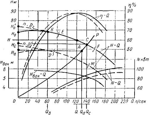
For the proper operation of the pump, it is necessary to know the relationship between the flow, pressure, power consumption and other parameters of this pump under various operating conditions. For this purpose, there are pump characteristics - graphs expressing the dependence of the pressure, power and efficiency of the pump on its supply at a constant number of revolutions (Fig. 42). These characteristics, sometimes called workers, are created when testing pumps in factory laboratories and are the main technical documents that determine the technical and economic properties of the pump.
From the approximate characteristic shown in Figure 42 (shown
Fig. 42. Performance characteristics of a centrifugal pump.
solid line) it is seen that for a certain and constant number of revolutions of the pump n its optimal mode corresponds to the flow Q and pressure H at the highest efficiency. With a closed gate valve on the discharge port, pump feed Q \u003d 0, the pressure is equal to H 0 (sometimes it reaches the highest value H 0), and power consumption N 0 It is approximately 30% of normal power N. After the valve is opened, that is, with the start of the water supply, the pressure in some pumps rises slightly and reaches a maximum, and then begins to decrease. Left ascending section ( H 0 V) curve H-Q characterized by unstable operation of the pump, since here the same pressure corresponds to different capacities. Operation of pumps with this characteristic is permissible only at flow rates exceeding the flow rate. Q in.
Pump performance with continuously decreasing curve H<Q (see site H 0 V) flows stably at all points of the curve.
Except curves H-q; N-q and h-Q, the graph (Fig. 42) also has a curve H vak -Qshowing the permissible values \u200b\u200bof the vacuum gauge suction height of the pump when applying the corresponding costs.
To expand the scope of centrifugal pumps that work with AC electric motors that do not allow changes in the number of revolutions (asynchronous squirrel-cage electric motors and synchronous), the outer diameter of the impeller is used. With a decrease in the outer diameter of the impeller by no more than 10-15%, the efficiency of the pump remains practically unchanged, and the supply and power consumption decrease. In accordance with this curve h-Q the graph will shift to the left, and the curves H-q and N-q drop and form whole stripes H-q (area) of the possible operation of the pump in question due to the specified operation.
It is recommended that the pumps be operated only in high efficiency areas. Therefore, not the entire strip should be used. H-q, but only its part corresponding to the permissible efficiency factor. In practice, it is allowed to reduce the efficiency factor by 7-10% against the highest value for this pump. The MDEF curved quadrangle limits the recommended area of \u200b\u200buse for this pump. Similar graphic characteristics are given in the catalogs for limiting cutting of impellers by no more than 10-20% of the normal diameter. Further trimming of the diameter of the impeller is not recommended, since in this case the efficiency of the pump starts to decrease sharply.
When trimming the impeller of a centrifugal pump, the supply and pressure are changed in accordance with the equations below.
(4 - 1) (4 - 2)
where: Q and H - supply and pressure of the pump with a normal outer diameter of the impeller D 2;
Q 1 and H 1 - supply and pressure of the pump with a cut off wheel diameter.
As a result of a joint solution of these two equations, we find that:
Using these equations, you can, for example, find to what size you need to cut the pump impeller to ensure the required flow rate Q a and pressure N a. For this, from equation (4-3) after substituting the set values Q a and On the find the coefficient kentering into the specified equation.
Further, asking two or three values \u200b\u200bof expenses on a scale Q graph (Fig. 42) and using the same equation (4-3), we can determine the corresponding pressure values. When calculating the pressure found value k in equation (4-3) is kept constant. By values Q and N should build a curve R-O, which will necessarily pass through a given point A with coordinates Q a and On the and cross the curve H-q at point C. After this, for example, according to equation (4-1), it is easy to determine the desired impeller diameter:

In pumps with guide vanes or seals at the wheel exit, only blade cutting is performed. In spiral type pumps (without guide vanes), both vanes and wheel disks are machined.
The impeller turning limit depends on the speed coefficient determined by the expression:
where: Q - pump flow, m 3 / s;
H - pump head, m at n, rpm
The following turning limits are recommended:
for wheels with n s from 60 to 120 .. ........... 20-15%;
" P s "120" 200. …………. 15-11%;
" P s "200" 300 .. ………… .11-7%.
purpose of work
2.1. Removing the performance of centrifugal pumps, representing a set of dependences of the total pressure N from his performance Q, when working together on a given pipeline with a constant impeller speed.
2.2. Removing network performance.
2.3. Comparison of the obtained characteristics with analytical representations of pressure-flow characteristics.
Brief theoretical information
Pump performance
The performance of the pump is called the dependence of its main parameters: pressure ( N), power consumption ( N), efficiency ( h), cavitation stock ( Dh add) from filing ( Q) This characteristic is individual for each type of pump.
Consider the pressure dependence N from filing Q. Examples of such characteristics are given below (Fig. 1.2).
The analytical dependence of the discharge characteristic for the NK pump is determined by the formula:
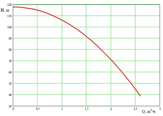
Fig. 2. Pressure characteristics of Grundfos CR pumps with different number of stages
Regulation of the pump flow by throttling.
Throttling - damping of a part of the pressure created by the pump by means of artificially introduced hydraulic resistance into the pressure or suction line (Fig. 3). Typically, throttling is achieved by partially closing the valve on the pump pressure line. This method is the simplest and most common, but at the same time the least economical, since part of the pressure created by the pump is uselessly spent on overcoming the valve resistance and the corresponding power is dissipated.
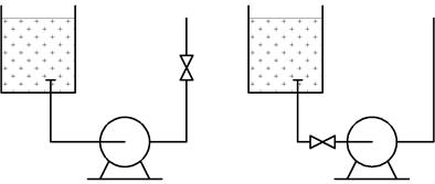
a) b)
Fig. 3. Regulation of the pump flow by throttling the pressure (a) and suction (b) sides
In fig. 4 shows the flow-pressure characteristics during throttling of the pump lines on the pressure line. Working point 1 corresponds to the pump flow Q 1. If, according to the operating conditions of the system, fluid should be supplied to it at a flow rate Q 2less consumption Q 1, cover the valve on the discharge pipe of the pump, reducing its flow (network characteristics 1, 2 correspond to varying degrees of opening of the throttle body). To determine the operating mode of the pump from a point Q 2 draw a line parallel to the ordinate axis. It will cross the characteristic of the system at a point 3 and the characteristic of the pump - at the point 2 . The difference in the ordinates of these points h w is excessive pressure, subject to "repayment" by the resistance of the valve.
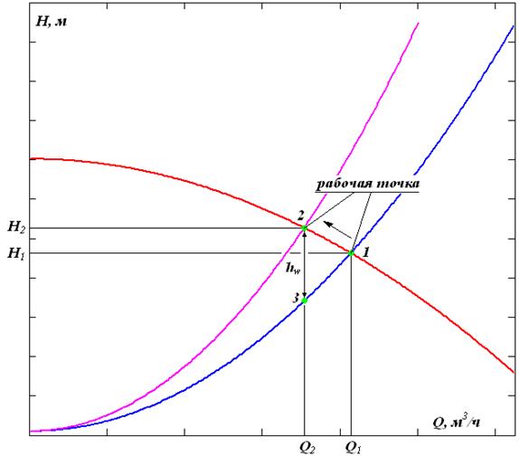
Fig. 4. Flow-rate characteristics during throttling of the pump line on the pressure line.
The method of regulation by means of a suction valve is economically somewhat more advantageous than regulation by a pressure valve, but its application is limited by the requirement to maintain a suction height that is less than the limit for ensuring normal operation of the pump.
By closing the valve on the suction pipe, the vacuum in it is thus increased, which is equivalent to an increase in the suction height. It should be noted that increasing the suction height above certain limits causes cavitation, makes the pump unstable and creates a risk of disruption to the pump.
The method of regulation by means of a suction valve is economically somewhat more advantageous than regulation by a pressure valve, but its application is limited by the requirement to maintain a suction height that is less than the limit for ensuring normal operation of the pump. By closing the valve on the suction pipe, the vacuum in it is thus increased, which is equivalent to an increase in the suction height. It should be noted that increasing the suction height above certain limits causes cavitation, makes the pump unstable and creates a risk of disruption to the pump.
In fig. 5 shows a network characteristic 2 pump 1 and reduced characteristics 1’ , 1” corresponding to varying degrees of opening a throttle valve on the suction pipe. The reduced characteristic is the characteristic of the pump, assigned to some point in the pipeline after the valve. To obtain a reduced characteristic from the taken point, the pressure losses are postponed in the area from the pump to this point. The difference in the ordinates of the pump characteristic and the constructed pressure loss characteristic will give a reduced characteristic.
The method of controlling the suction valve is especially advantageous with a gentle system characteristic. If, according to the suction conditions, regulation by the suction valve is permissible, it is more reliable to apply combined regulation by means of the suction and pressure valves.

Fig. 5. Flow-discharge characteristics during throttling of the pump line on the suction line.
The method of regulating the pump flow by changing the number of shaft revolutions is most effective from the standpoint of energy saving. At the same time, relatively cheap, reliable and easy-to-use induction motors are often used to drive pumps. The change in the number of revolutions of such engines is associated with the need to change the frequency of the supply alternating current. This method is difficult and costly. In this regard, throttling is mainly used to control the pump flow.
3. Description of the laboratory facility "Stream"
3.1. General information
This laboratory workshop uses:
1. centrifugal pump cantilever type Grundfos NK 32-125 ( further pump No. 1);
2. centrifugal multistage pump type Grundfos CR 1-19 ( further pump No. 3);
3. ultrasonic flowmeter "RISE"
4. pressure gauges digital DM.
Centrifugal pumps №1 and №3 connected using an elastic coupling with induction motors. Water is absorbed by the pump from the feed tank, the free surface of the water in which is higher than the level of the pump. In this regard, the pump does not require priming. A valve is installed on each suction pipe, which serves to create additional resistance on the suction line, as well as to disconnect the pump from the network during repair. Each discharge pipe has a valve for regulating the pump capacity and a pressure gauge for measuring pressure. The hydraulic system is closed, i.e. the pump draws in water from the feed tank and delivers it to the same tank. On the control panel of the pump installation, buttons for starting and stopping the pumps are mounted.